
Today I want to talk about protecting digital Inputs of AVR or any other microcontroller from over-voltages. When you look at most microcontroller circuits found on the internet shared by hobbyists, you don’t find any input protection. Some argue that this is not needed or don’t understand in most cases how it works. Let’s see how a simple resistor can save the day.
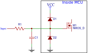
Lets see at simplified version of digital input of AVR microcontroller.

We can see there that input uses CMOS logic where the transistor is switched by voltage. According to the AVR datasheet, the gate control voltage should stay within the -0.5V to VCC+0.5V range. If we power our device with a 5V supply, we need to ensure that the pin input voltage stays in the range of -0.5 to 5.5V. When the input voltage source is taken from the same power supply, we don’t have to worry much about it. But what if AVR is accepting digital signals from other sources like sensors, other devices powered by their power supplies. Can we be sure that voltage will always be within safe limits? This is why there are two clamping diodes (sometimes called ESD protection diodes) used. They are here to protect logic from over-voltages and under-voltages. They do their work pretty well until they die.
Let us take a situation when the voltage at the pin is 7V. What happens here. D1 Anode voltage is 7V while the cathode is VCC=5V. Then we get 7-5 = 2V on diode. But diode forward voltage drop is about 0.7V. The diode becomes unprotected, and a high current flows through the diode until it fails. And so logic becomes unprotected. The same is with under-voltage. If we apply -2V at the input pin, then diode D2 starts conducting forward from GND to PIN with 2V across. Again voltage drop at diode is 0.7V, and so current grows until diode fails. And so, if we expect that input voltage may be off-limits, we need to add the current limiting resistor.

Now when we added a resistor, we have a place where voltage can be dropped. Like we had 7V on the input pin, and the diode forward voltage drop is 0.7V resistor takes the rest of 1.3V. What about current? It is not recommended to exceed 1mA on clamping diodes. Having this data, we can model the worst-case scenario. Let’s say we expect that input voltage spikes will never exceed 10V. Then we can calculate the current limiting resistor value:
R = (10V – 5V-0.7V)/1mA = 4.3kΩ
We can simulate this on Ltspice:

DC simulation results:

As we can see current on diode D1 is about 1mA and voltage to CMOS Vout=5.65V.
Going even further, there can also be a capacitor included which with a current limiting resistor makes the RC filter. Resistor part serves as current limiting resistor while capacitor adds filtering of glitches and debounces input signals.
You may need to calculate or model RC circuit individually.
What if you design the critical device and do not want to rely on clamping diodes inside AVR or another micro. In this case, you may add external clamping diodes. Even better – use Schottky diodes.

Schottky diode forward voltage drop is lower than a standard diode. It varies from 0.28V to 4.3V. So if over-voltage or under-voltage occurs, diodes will protect the circuit, and internal diodes won’t conduct at all. So you get a double defense in case any of the diodes fail.
Can there be more protection added? Of course. If you are likely to work with high voltages – like building a microcontroller-based HV zapper or there is a chance to catch high voltage on input, the first line of defense should be a transient voltage protection circuit. These can be based on varistor, gas discharge tube. But probably most reliable in such a situation would be using transient voltage suppression diode (TVS). They can handle high peak currents and clamps fast. This is how heavily protected pin would look like:
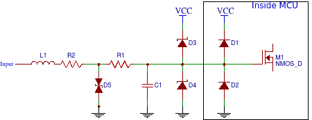
You can use ferrite bead L1 before the TVS diode, which slows down the voltage’s rise time, giving enough time for the TVS diode to turn on. Probably you are not likely to build such protection as this is overkill and quite expensive per pin. But in some industrial applications, you can find such solutions.
Generally speaking, if you are designing a hobby circuit that will be battery operated, then probably input voltage will never exceed limits, and so you can omit resistor. And this is how most hobby circuits are built. Nothing wrong with this. But if you are designing a device for the market and there is any risk of over-voltage, you must include a current limiting resistor. Resistors are cheap, so adding them won’t hurt anyway.
Thanks, your article is clear and most helpful. Any further advice on calculating the capacitor on the input RC filter?
Hey, same question as above 🙂 Could you help with a values for 3.3v pins?