
In the specifications of operational amplifiers, there are maximum limits of allowed voltages on pins. Maximum currents are limited as well. So voltage and current they both limit allowed dissipated power Pmax=Umax*Imax.
In well-designed circuits, Op Amps should have protection circuits from various overloads like a short circuit, high common phase voltage level in differential inputs, electrostatic charges, etc.
Earlier operational amplifiers didn’t have built-in protection circuits, while modern ones have. Today popular operational amplifiers have internal protection circuits built-in, and this makes designers’ life much easier. But protection elements lowers some operational amplifiers like operation speed, dynamic range, and output signal swing level. Because of this, some operational amplifiers may not have internal protection circuits. In this case, you have to take care of it.
Protection from the high differential voltage input
When protecting Op Amps from high voltage inputs, usually there are protecting diodes connected between input pins.
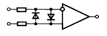
In normal operation (linear mode), when the signal input level is up to mV, diodes’ resistance is few mega-ohms. Practically diodes do not influence the input signal. But when input voltages open diodes, then input voltage will be limited to a few milli-volts (p-n junction voltage). To limit the current flowing through diodes, there are resistors needed on each pin.
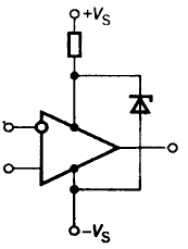
Short circuit protection
Many op-amps have built-in protection from the short circuits but not all. So, where protection is needed, there can be a resistor connected to the op-amp output. The resistor has to be connected with feedback – then dynamical output resistance stays low.

The resistor value should be minimal, allowing to pass maximally allowed current at voltage applied. For instance, if the operational amplifier’s maximal current is 15mA and the voltage applied is 5V, then resistor value 169Ohm. A resistor connected to the op-amp output lowers the dynamical range.
Protection from the high common phase voltage input
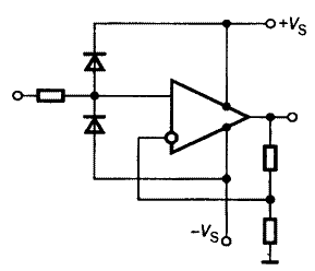
In this case, if voltage exceeds limits, then one of the diodes opens this way voltage in noninverting input fixes at supply voltage. Input current starts flowing to the supply source, and if there is a voltage regulator as a supply source, then there may be the situation when it may start to produce higher voltages on load. To protect circuits from this, there should be a Zener diode connected to the supply circuit.
Protection from overvoltages on output
If the circuit connected to op-amp output has inductive elements, then the rapid growth of output current can be over-voltages occur. This way output pin has to be connected via diodes to supply pins:
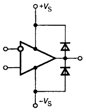
depending on over-voltage polarity one or another diode opens.