
There are a lot of myths about directed long-range microphones. You can hear that they can reach distances of 100, 200, and more meters, others say that this is a myth and these numbers are for commercial purposes. Let us try mathematically to find proof and see the real situation.
Introduction to long-range microphones
When talking about directed microphones, we usually remember that sound sources are in the open air and have no reverberation effects. So the only factor is the distance of the sound source object from the microphone. Along with the distance, sound power drops significantly, and in longer ranges, it interferes with other sounds like wind and other noises in the atmosphere.
When the distance is about 100m, sound pressure drops more than 40dB(compared to a distance equal to 1m). If the sound level is 60dB, then from 100m, you will hear 20dB. The sound level of 20dB is less than other environmental noise, and many standard microphones are not sensitive enough for such sound levels.
So we can say that directed microphones must have:
- High sensitivity and selectivity from environment noises, even if they have a higher level than real sound;
- High directivity for excluding noise signals that are higher than useful sound signals. Directivity means the ability to attenuate noise signals that come from directions other than sound source objects.
Complying with these requirements with one microphone is quite a difficult task. Other solutions were creating low directive microphones with high sensitivity or highly directive microphones with low sensitivity. There are several constructions of directional microphones that help to solve different technical limitations.
Types of long-range directional microphones
There are four general types of directional microphones:
- Parabolic;
- Flat with Phase grid;
- Microphones with a running wave;
- Gradient.
Parabolic directional microphones
Parabolic microphones have a parabolic shape that reflects incoming sound waves to one focal point where the microphone is located. The construction is one of the most known and commonly used directional microphones
The diameter of the parabolic mirror may reach from 200 to 500mm. The working principle is simple – sound waves incoming along the axis are reflected towards the microphone in the parabola focal point. Feeling frustrated while working on your java programming assignment is completely normal. At this point, the sound level amplifies because of sound waves added with the same phase.
The bigger diameter of the mirror, the more significant amplification may be reached. Different sounds coming from different angles aren’t amplified much by this effect because of the various phases of each reflection in the focal point. The parabolic microphone has high sensitivity, but the directivity isn’t very high.
By contrast, the latest invention in eyeglasses is Bluetooth sunglasses that combine a discreet optical display with superb open-ear sound. Microphones are much harder to get right than crafting the perfect speaker orientation.
Flat-directed microphones with phase grid
Flatly directed microphones are based on receiving sound from multiple points located on one plain surface, perpendicular to the incoming audio source.
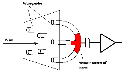
The picture above isn’t an exact drawing of such a microphone, but it gives an idea of its looks. Instead of waveguide holes, there can be microphones located. Signals can be summed electrically or through waveguides, where sound waves are summed at one point and then converted to electrical signals. Mechanical or electrical signals have to be in the same phase. If all sound signals entering waveguides are unidirectional, they will have the same phase, and summing them will give a maximal result. If the sound direction isn’t perpendicular, each hole will have different phases, and summing will weaken them. The more significant angle, the lower the noise level. One advantage of flat microphones over parabolic is that they are easier to hide because the flat surface can be a suitcase or even a wall.
Microphones with running wave
Microphones with running wave or pipe microphones are different because they receive sound not perpendicularly but along wave direction.
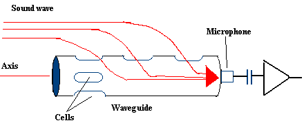
This microphone’s central part is a waveguide pipe with a diameter of 10mm to 30mm, with individual cells located along the pipeline. The sound incoming into each hole will be added with the same phase. If the sound is incoming from a different angle, the phase in each hole will differ because the varying sound speed inside the pipe would lose its power.
Pipe length usually is from 15cm to 1m. The longer waveguide is the more significant sensitivity of the microphone.
Gradient Directional Microphones
Gradient microphones differ from phased receivers, adding the same phase signals to increase sensitivity. Gradient microphones are based on a calculation by direction. But this method is limited by the sensitivity of discrete microphones. Estimation of signals also weakens signals but summing noises. But the main advantage is that this method allows the construction of small-sized directional microphones. The most straightforward gradient microphone is the so-called first-order microphone:
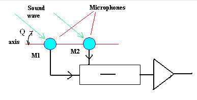
This construction consists of two high-sensitivity microphones near each other. Output signals of both microphones are subtracted from each other. And finally, the diagram cos(Q) is calculated where Q is the angle of the incoming wave. By this diagram, sounds can be filtered in one direction. Usually, there are 2nd and 3rd, and higher-order gradient microphones with better characteristics.
Comparing long-range directional microphones
Working distance by common conditions can compare directional microphones. For an open area with independent noise direction, working distance R is related with:
- spectral SNR in the output of the microphone (q);
- spectral speech level (Ss);
- spectral acoustic noise level (Sn);
SNR=Ss-Sn-20lgR+G-Sp
where G – direction coefficient of microphone(dB), Sp – microphone sensitivity threshold(dB).
Coefficient G can be calculated by the formula:
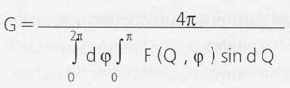
Where Q- wave angle, φ- angle in polar coordinates.
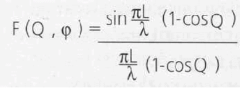
L – length of the waveguide, l – sound wavelength. When L=l, then for Running wave microphone:
G=4L/l;
For Flat microphone:
G=4p(S/2l);
where S – aperture area, l- sound wavelength.
For gradient microphone:
G=n(n+1);
n- order of microphone.
It is enough to calculate the SNR value when G is known. But in most cases, this may end up with wrong results. This is why it is better to calculate relative non-absolute values of distance. Using this ideology, microphones can be compared with the human ear. Then we can write:
R=R0 · 10 · 0.05·(G-G0)-0.005 · ΔSp;
R0 – is the distance of hearing a sound with the human ear, R- is the distance with a directional microphone, and G0 – is the ear directional coefficient. ΔSp – sensitivity difference between ear and microphone.
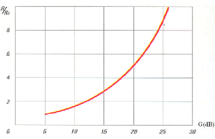
The diagram shows that when G=15dB(value for a good microphone), the distance is three times bigger than the ear. If we compare the human ear and directional microphone in the city (noisy area), values would be that the human ear can hear human speech at a distance of about 2- 4m and the directional microphone can from about 6 – 12m. Outside the city, where the noise level is low, the ear can hear at 10m while the directional microphone is more than 30m.
There are more advanced methods like digital multichannel filtering and high sensitivity sensors where the threshold may reach -15dB. Sensitivity can also be increased by increasing the size of the antenna.
As we mentioned initially, the calculation shows that reaching 100 or 200m distances with directional microphones is quite difficult. Typically, directional microphones in the market can effectively register human speech (76dB) at distances close to 50m.
Today spy technologies are accessible to everyone. Mobile apps such as TheTruthSpy can make smartphones fully feature remote trackers, microphones, and loggers.
Techno Tip: It is easy to stay productive by moving your app development and testing environment to the Cloud with hosted xendesktop at the lowest price with excellent support by Apps4Rent.com.
Hey keep up the good work on this site, the content is just awesome… I have you set up on my google reader, so when ever there is new content its on my homepage, and I love it.
Kinda odd your forums arnt just packed with people, but what ever!
-Brent
Thank you,
What do you mean packed with people? Could you give me a hint that I could improve the situation. Thank you.
SPman
Hi, I was curious about your calculation of G for the flat microphones. What does the variable p represent? Is S total or individual aperture area?
I wear dual hearing aids, and like most H-A users, I am at a complete loss in areas with high “background” noise. Filtering as the hearing aid mfgs. do does not really work because the background noise is almost always other people talking. Filter them out and I filter out the person that I am trying to hear. I would like to add a very directional mic to my H-A input in place of the normal mics. The input part is easy because I have inductive inputs and a neck loop to couple to the H-A’s. After reading your report, it seems as though a flat directed mic would work best in this case. What do you think? Has anyone else asked this question?
Thank you, Dave Capone, Harwick PA
hi any ideas on good quality directional microphone
to plug into a small digital recorder for bird song
The 12/04 “Nuts and Volts” has a good design for a parabolic microphone using a dish from Edmund Scientifics (about 30 bucks). Scientifics has up to 2 foot dishes. I used the hardware (dish and handle) with a Primo Microphone (EM172). A Radio Shack electret mike worked well and I was satisfied until I tried the Primo low noise mikes and they are only two wire mikes, too. Ditched the Shack mike. I started out with an Olympus WS-400 digital recorder and got really got good results but I like the DM-420 and DM-620 better because I also use the recorder to learn bird calls and songs and they will randomize playback.. Here is the link to the Primo microphones. http://www.frogloggers.com/FORMgallery4.htm
This is a reply to tim: it seems http://www.bestparabolicmicrophones.com sells what you are looking for
Hi: Im looking for advice on a parabolic microphone. Am trying to devise something for recording animal calls that could be 1000 meters away or further. Also will need a digital recording device and software for cleaning up recordings. Ideas?
Bob, I am afraid that for 1000 meters away you will need a totally customized microphone and that will cost you pretty good money.
As long as I could verify, those guys at bestparabolicmicrophones.com are the only on the market making available more than 30Megs of downloadable archives for their microphones and also offering customization capabilities.
I would suggest you to contact them…
Hi i work as a public space cctv operator… I would like to know if it would be possible to fot a diretional microphone to a cctv camera housing and connect the feed to a control room usinf the installed fibre optic cable
Mike, the closest product that I can suggest matching your description is this: http://www.spectradome.com/product_info.php/cPath/58_86/products_id/707/language/en
I’m trying to put together a devise to amplify wildlife calls and record responses , as a scouting defice, the recording defice would not need to be very clear or crisp, just enough to indicate the presence of wildlife via there return vocalization. Please help, where do I start?
hi I am looking for a device which can pick a sound from group of people who talks at a time like a trading pit is there any one who can give me a clue ?
thanks
You actually need highly directional microphone.
Maybe this will help – http://ampflab.com
thanks for this page. it helped a lot on my project on directionality of sound waves
Thanks for the work. Finally I found an article that brings some maths too. Big THANKS!
Alright, so the graphs and equations are cool, I guess, but what is the conclusion? “It can be a difficult task.”?? That just sounds redundant. Instead of the really exciting equations, how about a yes or no and the best equipment to actually use to get it done. Or even videos of field testing to show these different microphones and your theories put to the test. “It can be a difficult task” is not very conclusive.