There can be any external device that may be connected(interfaced) to the microcontroller. They may be for control input like buttons, keypads, touch, or information output, e.g., display, sound, motor, relay, and modem. Also, output devices may be further chips like transmitters, frequency generators, memory. Interfacing with chips is not that hard because most of all (especially digital ones) are TTL level compliant that allows connecting chips one to another directly. Otherwise, there are TTL level converter chips if needed – like RS232 to TTL converter MAX232 chip.
Let’s take a simple device LED. Probably many of you are thinking that there is nothing easier than connecting LED to the microcontroller. Yes, it’s true. Considering AVR microcontrollers, Led can be connected directly to port pin via limiting resistor either as a source either as drain because the chip can provide enough current to light diode without damaging the port. But what if you need to connect like 10 LEDs when each requires, let’s say 20mA. The total current would be 200mA. No tall microcontrollers can provide such power directly without damaging the port. The simplest way to avoid this problem is to use LED via amplifying transistor.
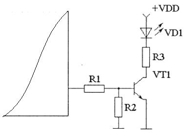
The transistor acts as a current amplifier that can provide LED with the needed current without any microcontroller damage. Such connection may be used in any digital circuit as the transistor accepts any control signal (TTL, CMOS) and amplifies it to the level needed for LED or another device. R3 resistor is current limiting for LED and transistor itself, of course. It is easy to calculate the R3 value. Let’s say the diode requires ID=20mA transistor can handle 100mA, VDD=5V, then R3=VDD/ID=5/0.02=250Ohm. It is good practice(especially for indication purposes) to suggest take a little bigger resistor value to ensure reliable work. R1 and R2 resistors act as voltage dividers. But for a 5V system, you may exclude R2 as 5V is OK to connect to base via like 1kOhm resistor. There can be a Darlington array driver (ULN2002) instead of the distinct transistor for a more compact solution. Each Darlington transistor may source up to 100mA of current, making it ideal for interfacing LEDs, motors, and relays compactly.
You want to interface with more powerful devices like a light bulb or other device powered from 110 or 220V. For this, you need to modify the previous circuit by adding a relay instead of a diode. This time you don’t have an option of connecting the relay directly to the MCU pin for several reasons, like the relay is an inductive load, which can generate voltage spikes during switching that may be strong enough to damage the microcontroller port. Relays also require more current than the port can handle.
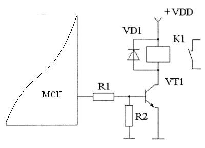
It is important to add a VD1 backward diode, which protects transistor high voltage ‘spikes’ produced when the relay coil switches.
Input devices can also be connected in many ways. I bet probably most of you know how to connect a single button to a port pin. Usually, the button is connected to the ground with a pull-up resistor.
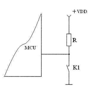
Some microcontroller types like AVR have pull-up resistors built inside the chip, so you only need to connect the button to the ground and switch the pull-up resistor in software. Reading of button state is simple. If the button is pressed, the port reads 0; if not port pin value is 1.
Let’s take a simple example of a 4×4 button keypad input device. Keypad usually is organized as crossed rows and columns if button matrix. Such a keypad may be read with half of the pins configured as input and another half as output. Most microcontrollers allow configuring separate pins of the single port as inputs and outputs.
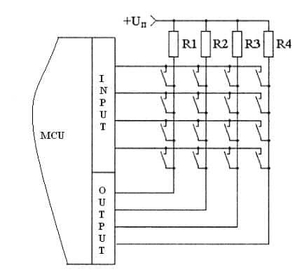
A matrix keypad is a bit more complex. Scanning columns do keypad reading. So loop sends 1 to each column(or row-it doesn’t matter), and then the microcontroller reads all rows by checking if any of the pins have 0 levels. If none of the buttons were pressed, all input pins would be at 1 level.
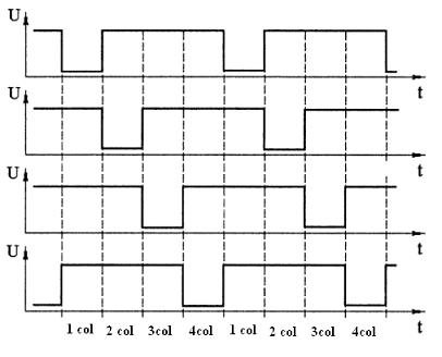
If one of the buttons were pressed, then on pin reads 0. Because we know which column was set to 0, we can define which button was pressed by crossing row and column. This way it is possible to interface more buttons that there are free microcontroller pins. With one 8-bit port, you can interface 16 buttons.


There is actually an error here….
R3=VDD/ID=5/0.02=250
it should really be R3 = (VDD – Transistor junction voltage drop) / ID