


Post updated with new screens and up-to-date information (2020)!
There have been several requests from users to explain more about loading programs into the flash memory of STM32 microcontrollers. There are several ways how to perform stm32 flash programming.
- You may enter the STM32 bootloader directly via USART interface and upload the binaries.
- The more advanced and flexible method is to use an ST-LINK utility – an ST-based adapter, which connects to STM32 board through JTAG interface. Many ST development boards already have this feature included. Otherwise, you can jump-wires from one to another, or get a dedicated portable ST-Link adapter.
- Also, you can use standard third-party JTAG tools such as J-Link.
- Finally, you can flash your bootloader that works with any interface (USART, USB, SPI, etc.)
The STM32F103RB board
Any of these methods are great if they get the job done. In this topic, let us focus on how to perform STM32 flashing by using a bootloader. Today probably, no manufacturer is producing boards with an RS232 interface. Nevertheless, you like me, probably have a dozen older boards with a serial port. They are great boards still to use in many projects.
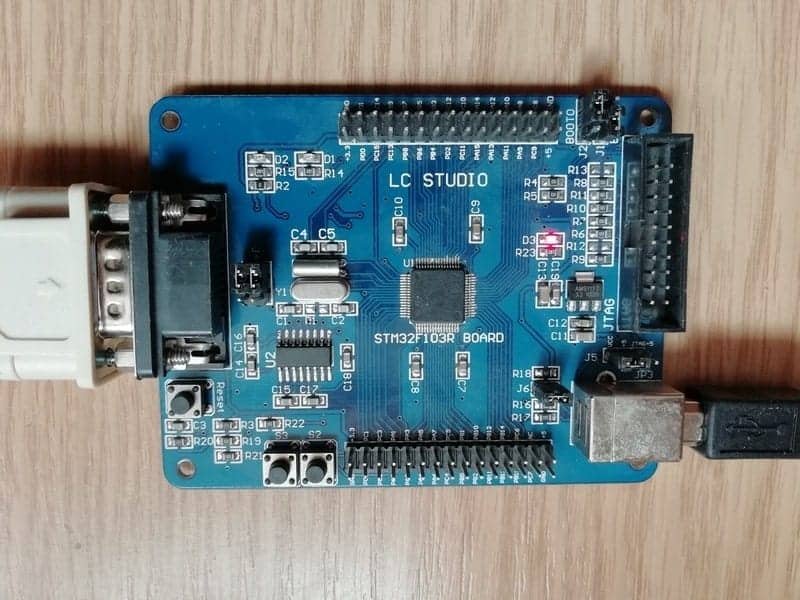
In my example, I am using an LC STUDIO project board, which features electronic components such as:
- M3 STM32F103RBT6 ARM Cortex processor
- Flash – 128KB
- SRAM – 20KB
- Three 16-bit timers
- 1 SysTick timer
- SPI 2 (up to 18 Mbits/s)
- I2C 2 (support SM Bus 2.0/PM Bus)
- USART 3 (one up to 4.5 Mbit/s, other two up to 2.25 Mbit/s)
- USB 1 (compatible with the USB Full-speed 12 Mbs)
- CAN 1 (up to 1 Mbit/s)
- ADC 12-bit: 2 ADC – 16 channels
- 1 RTC
- DMA: 7 Channels
- Internal Temperature sensor: 1 (internally connected to the ADC_IN16 input channel)
The LC STUDIO development board has the following features:
- 1 Serial RS232 Connector (MAX3232 chip-level converter, USART1 or USART2 selected with jumpers J4)
- 1 USB Connector (mapped to PA11 and PA12 pins)
- 1 JTAG Connector (2×10 header)
- Reset push-button
- 1 Power LED
- 2 User push-buttons (mapped to PC0 and PC1 pins)
- 2 LEDs (PB8 and PB9 pins)
- J5 Jumper for selecting power supply (from the USB connector or JTAG connector)
- J6 Jumper for activating USB Pull-up resistor (R18=1.5k)
- BOOT0 and BOOT1 jumpers for selecting boot mode
- LC filtering for VDDA (L1 and C6)
Using serial cable or USB to serial adapter
Probably you have a newer computer that may not have a serial interface. There are two ways of solving this problem.
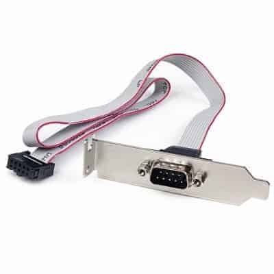
Check your motherboard if it has a serial interface connector. This way, you can get a cheap external expansion connector, which connects to the motherboard.
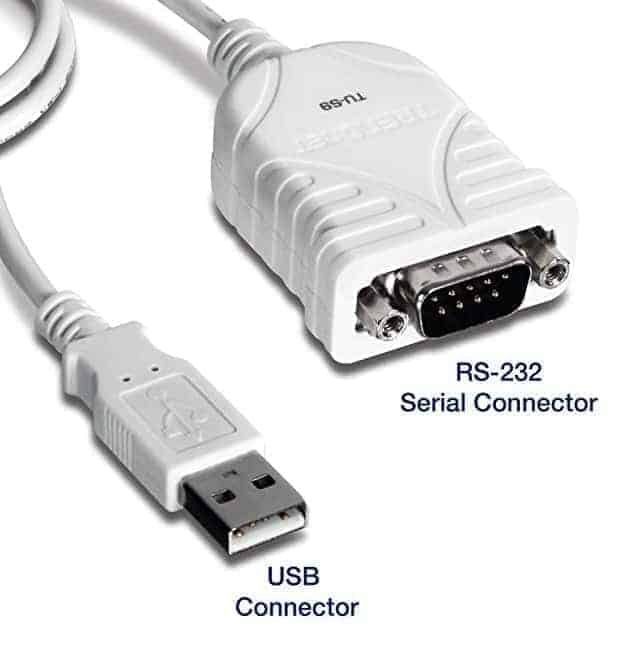
Alternatively, you may use a USB serial cable which works just like a serial port but links to the USB port.
Most USB to serial cables are recognized automatically by operating systems, and no additional actions are needed. There may be some weird cables with unrecognized converter chips. This way, you will need a driver from the manufacturer. The best advice is to stay away from suspicious cheap cables and use known brands.
The embedded bootloader on STM32
All the STM32 microcontrollers come with built-in bootloaders that burned in during production. Depending on device type, flash memory can be flashed using one of the interfaces like USART1 or USART2, USB, CAN.
We are mostly dealing with low, medium, and high-density devices to access bootloader using the USART1 interface. USART1 can be accessed directly via the RS232 interface or USART to a USB driver chip like FT232.
A couple of special MCU pins have to be set-up to proper logical values to enter the bootloader. The pins are named BOOT0 and BOOT1 on the STM32 microcontroller. Boot pins can select several modes of bootloader operation:
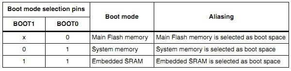
As you can see, there are three cases:
- The first case is when the BOOT0 pin is tied to the ground, and BOOT1 is open or at a logical state of 0 after the reset program is executed from Main Flash Memory. Grounded BOOT pins are a standard configuration when executing programs in the field.
- The second case (BOOT1=0; BOOT0=1) means that after reset execution starts at System memory were built into bootloader resides. This is the case when we need to upload binaries via USART1.
- The third case means that program execution is performed in SRAM.
Let us focus on the second case – System memory. You will find a couple of jumper pins in most of the development boards where you can select BOOT0 and BOOT1 configurations. In our case, the STM32F103RBT6 board looks like this:
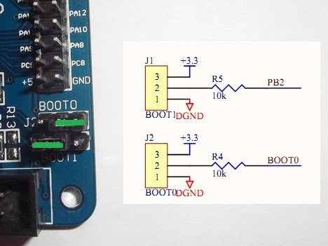
In the image above, you can see that the jumper setting is already selected to run the internal bootloader after the restart.
Flash Loader download
To access the bootloader, you need special software called Flash Loader Demonstrator, also known as FLASHER-STM32. Be sure to get the latest version to have proper support for the newest operating systems like Windows 10.
Install it and launch. You will see the screen where you will be able to select USART parameters. Be sure to select the correct COM port:
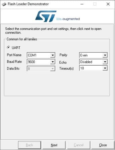
Connect the board to the PC using your preferred cable and hit the Reset button before further action. You may need to find a working Baud Rate which for my STM32F103R is 9600. After you click the Next button, the next screen opens.
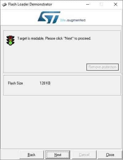
It confirms that you successfully entered the bootloader. The flash loader detects the flash size of the device, which, in my case, is 128KB. Hit the Next to proceed to the device selection screen.
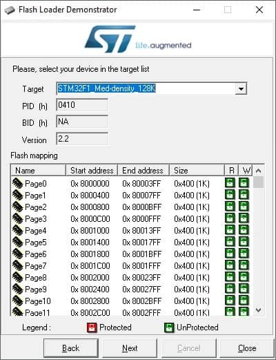
As you can see, the target device is highlighted automatically. If not – select the right one from the drop-down list. Bellow, you can also see the other information like bootloader protocol version (2.2), and Flash memory mapping. Click Next if the selected device seems OK.
STM32 flash programming
flash_loader_demonstrator_programming_screen
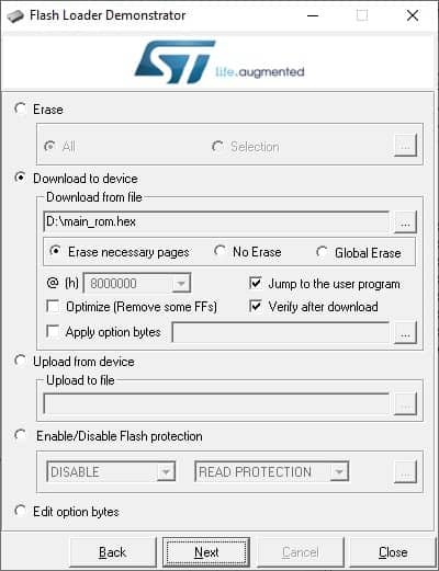
Finally, you get to the screen where you can do all sorts of things:
You can erase all or select memory pages. Download a .hex (.bin or .x19) to STM32 microcontroller flash memory.
Select Jump to the user program if you want to execute a code immediately after download.
Additionally, you can select Verify after download to make sure if the upload was successful.
You can also Upload from device an existing binary from device Flash memory to the file and back it up for later use.
There is an option to enable or disable Flash protection from reading or writing.
Finally, you can go further with the Edit option bytes to set unique settings bytes, write, or read protections of selected memory pages. These settings are often used in the production phase with the purpose to protect from copying the code.
Let us download a .hex binary file to STM32 device flash memory. You need to browse for the binary file in the field Download from a file. In the dialog menu, select to verify after download and jump to the user program like this:
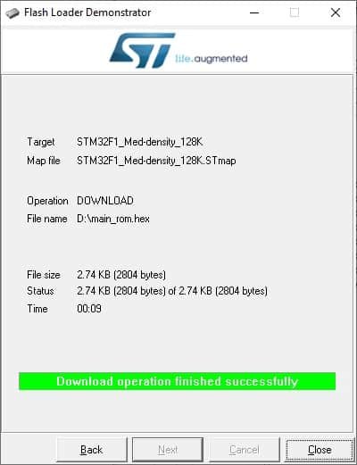
Hit the Next button to start programming and verification.
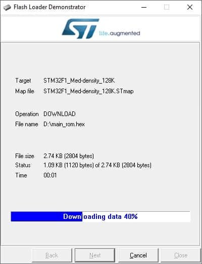
In a few seconds, it is complete. The download time may depend on binary size. My example binary size is 2804 bytes, and it took 9 seconds to upload and verify.
Executing microcontroller code after reset
When flashing is finished, if Jump to the user program checkbox was selected, your program is executed immediately. To run your code normally after resetting the board, you need to return the BOOT0 microcontroller pin to the ground by moving the jumper.
Read more on ST-Link flashing and J-Flash stm32 flash programming methods.
Dear friend,
On my board LEDs always blink. Is it correct?
It depends on what your program really does.
thank you for your information but I would like to program the STM32-P103 board RS232 I used this technique but it always shows me an error ” No response from the target, the Boot loader can not be started, please verify the boot mode configuration and the flash protection status, Reset your device then try again…”
I do not know how to solve it thank you for helping me
Hi,
I am trying to program a stm32f103c6. I have the boot1 =0 permanently. boot0=1 for programming. However i keep getting the error “no response from the target”. PLZ HELP.
Hello guys,
Is it supported for the STM32F030 devices?
Dude select proper boot pins , press rest button and try
Where to download main rom for stm32f103c BluePill