


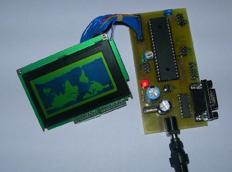
Once I’ve got several HQM1286404 graphical LCDs around, I decided to build a prototyping board where I could easily plug LCD to it, read data via ADC and display graphs, and plug keypad if needed for some menu functions. Earlier, I tested graphical LCD on prototype breadboard but dealing with multiple wires (GLCD needs 20) resulted in many failures. It is OK to do simple tasks, but more complex applications require a more stable platform. So here it is:
This type of GLCD is a standard 128×64 pixel matrix controlled by the KS0108 LCD controller. I have a smaller non-common pin-header where pins have 2mm step, so I had to draw it for Eagle library, which you will find in project files. I decided to make a simple circuit so it could fit in 100x50mm single-sided PCB. As base MCU, I used Atmega16, which can be replaced with Atmega32, which is pin-compatible with Atmega16 have more data memory.

The main features list:
- Atmega16 or ATmega32 microcontroller;
- High speed with 16MHz quartz;
- Can be programmed ISP;
- RS232 Communication with on-board MAX232;
- Adjustable AREF;
- The voltage regulator on board with power LED;
- Graphical LCD connector;
- 3 ADC inputs;
- 10 I/O pins for custom use;
- 100x50mm easy to build single-sided PCB;
- Reset button.
PCB overlay for quick pin finding:

Working with graphical LCD is really simple. Just find a suitable KS0108 library and you can output information with few commands. If you work with the WinAVR tool-set, I recommend downloading KS0108 Library which was written by Fabian Maximilian Thiele some time ago. As his site link is dead you can download it from here.
It is easy to add new characters to this library. Just download GLCDFontCreator2, and with this java program, you can fetch fonts from your windows system and automatically convert them to character arrays and save them in .h format ready to include in to project.
Download Eagle schematic, PCB and sample avrgcc project.
The board has no RS232 part soldered yet in a picture. It works without it for now. It will be soldered when needed.
Updated picture with all soldered components. Added:
AREF potentiometer, AVCC 10uH inductor, MAX232 and DB9F connector.
hi please guide me about graphical lcd connection model j12864e-7 thanks a lot and best regard/hamid
nice tutorial
this link i found some more projects on 128×64 Graphics LCD Module
http://onlinetps.com/shop/index.php?main_page=product_info&cPath=69_107&products_id=511
(check in product discription)
hi i want to know tht i am using glcd and when i connect to proteus it works but not in real world can u please help me wht cud be the reason i dont even see a grabage values on glcd please help me
i am using atmega 32
LCD Module @ AORAN
More many different alphanumeric types ,graphic types, give you plenty to chose from- 1×8 to 4×40 character displays ,122×32 to320x240 Graphic displays. Standard backlight options of low-power electroluminescent, high-brightness EcoBrightTM non-powered backlight by special order. LED or CFL backlights, low profile edge light options for thinner displays.
Standard or wide-temperature (-20°C to +70°C) operation. All parts can include an HD44780 compatible controller which can be ordered in either: Standard, European, Cyrillic, Russian, or Greek font options.
With more than hundreds different combinations in our regular range, we have the display for your application. If we haven’t, we can always fully or semi custom them for you!
Your blog has such a great information. Thanks for sharing it!
Hello it is really great tutorial. I have interfaced ATmega32 as per your circuit diagram but it is not working on real hardware. It is urgent required me too do this project please help me.
Thanks in advance