
HQM1286404 is a pretty old graphical LCD module, but it is still popular. KS0108 driver controls this LCD. LCD backlight color is yellow-green. I think this is an excellent choice for many projects where graphical information is needed for several reasons – you can find libraries around the internet to start working in just a few minutes. Several tools can also be used to generate character arrays and graphics.


The hardest thing for me was to find the correct wiring as the datasheet I have was for the next PCB revision (HQM1286405) as mine are HQM1286404, so don’t be mistaken as I did. Here is the correct pin-out of LCD:
1 Vcc
2 GND
3 VCON
4-11 DB0-DB7
12 CS2
13 CS1
14 RESET
15 R/W
16 D/I
17 EN
18 Vee out
19 LED Anode
20 LED Kathode
And circuit part how it is connected to my Atmega8:
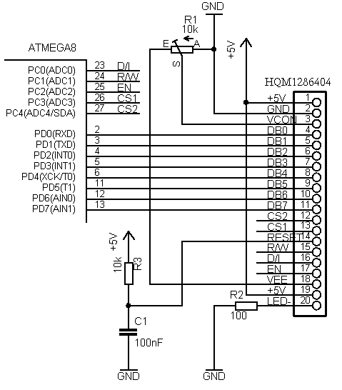
Chip select pins are in reverse order, so if halves of the screen are swapped, you have to swap wires. At VEE pin should be negative voltage near -4.9V. Potentiometer through VCON pin controls LCD contrast. The reset pin can be connected directly to the microcontrollers reset circuit. In my case, it is separate. The backlight LED can also be adjusted with another potentiometer is omitted here too.
When the circuit is ready, it is time to give it a try. For this, I recommend downloading the KS0108 Library, which can be found on the internet. I tried several, and only one was working correctly. Without digging too deep, use it for now. The library is written pretty some time ago by Fabian Maximilian Thiele. As his site link is dead, you can download it from here: KS0108 Library.
The good thing with this library is that it is easy to add new characters. Just download GLCDFontCreator2, and with this java program, you can fetch fonts from your windows system and automatically convert them to character arrays and save them in .h format ready to include in to project. Simple examples you will find in the library. I added a simple bitmap display function to it, which allows displaying 128×64 graphics. I convert BMP files to character arrays with the fastlcd.zip program. This program exports to .bas file, but it is easy to change to c compatible data – open generated file with notepad and select replace &h to 0x; then you can copy array data to c program.

My example, which displays simple graphics on LCD: Bitmap display demo program, is ready to be compiled with the latest WinAVR and flashed to Atmega8 via avrdude.
Updated code with Markus library fix: GLCD5
I tried compiling your code with latest version of WinAVR, but I am getting following error.
/usr/bin/sh: avr-sizex: command not found
make.exe: *** [sizeafter] Error 127
> Process Exit Code: 2
> Time Taken: 00:01
How do I solve it?
This error pops after compilation. This means that compilation was successful. I have updated Makefile with newer version;, where this error doesn’t show up.
Great article. I am working on a very simular display with the Arduino. I was just starting to work on the character display funcitons. Your article will help me greatly. Thanks!
It seems your pinout for CS1/CS2 is wrong way, the signals are inverted
No CS1/CS2 is connected correctly. Check out my board where same order is used:
https://scienceprog.com/diy-avr-graphical-lcd-test-board/
I tested again and I’m pretty sure pin12 is CS1, pin13 CS2. They are active low. You possibly dont see a difference if you change connection and handle them as active high. You see the difference when you activate _both_ signals so that both half sides of the display will be controlled together.
Hello All,
I tried to print messages on the lcd screen using ks108 library but not working . Can you please tell me how i can do that. i also tried test example of this library still not working. How i can convert colored bmp image into hex file so that i can get display it onto the display in monochrome.
mukesh
Nice article, it helps me more on shifting 8051 to AVR.
Guys i’m working on a 122*32 graphical lcd.(18 pins).
i’ve got all my hardware and initializing correct but still i’m unable to get even a pixel on. I’m using Freescale MC9S08DN60 controller.
can someone help me with the exact sequence of initialization and yes better if with the writing a command or reading it from lcd.
Hi,
Is there a way to get the complete code for this project and I’m trying to cut on development time. I need to use at least an atmega32 so I will have to have access to edit the source of the object files.
TIA
Vic
I’m using ATmega8, connection is triple checked, and it’s not working! I’m using Lumex LCD module.
Iam using LGM12864B display and atmega16 controller. can any one help me please
thank you
thanks man, your article had help me a lot much.
i would need a step by step pictures guide on how to wire it please can you help I beg you 😀
LCD Module @ AORAN
More many different alphanumeric types ,graphic types, give you plenty to chose from- 1×8 to 4×40 character displays ,122×32 to320x240 Graphic displays. Standard backlight options of low-power electroluminescent, high-brightness EcoBrightTM non-powered backlight by special order. LED or CFL backlights, low profile edge light options for thinner displays.
Standard or wide-temperature (-20°C to +70°C) operation. All parts can include an HD44780 compatible controller which can be ordered in either: Standard, European, Cyrillic, Russian, or Greek font options.
With more than hundreds different combinations in our regular range, we have the display for your application. If we haven’t, we can always fully or semi custom them for you!
thanks man, your article had help me a lot much.
Hello all. I am beginner and I’m learning c. In the function ks0108DrawLine that I report here (derived from ks0108.C code of Maximilian library ) ,
can you show me where the data is written into the KS0108 memory ? I don’t understand how te struct work.
Can you help me?
Thanks .
Fabio
void ks0108DrawLine(uint8_t x1, uint8_t y1, uint8_t x2, uint8_t y2, uint8_t color) {
uint8_t length, i, y, yAlt, xTmp, yTmp;
int16_t m;
//
// vertical line
//
if(x1 == x2) {
// x1|y1 must be the upper point
if(y1 > y2) {
yTmp = y1;
y1 = y2;
y2 = yTmp;
}
ks0108DrawVertLine(x1, y1, y2-y1, color);
//
// horizontal line
//
} else if(y1 == y2) {
// x1|y1 must be the left point
if(x1 > x2) {
xTmp = x1;
x1 = x2;
x2 = xTmp;
}
ks0108DrawHoriLine(x1, y1, x2-x1, color);
//
// schiefe line 🙂
//
} else {
// angle >= 45°
if((y2-y1) >= (x2-x1) || (y1-y2) >= (x2-x1)) {
// x1 must be smaller than x2
if(x1 > x2) {
xTmp = x1;
yTmp = y1;
x1 = x2;
y1 = y2;
x2 = xTmp;
y2 = yTmp;
}
length = x2-x1; // not really the length 🙂
m = ((y2-y1)*200)/length;
yAlt = y1;
for(i=0; i= 100)
y++;
else if((m*i) 0 <= -100)
y–;
ks0108DrawLine(x1+i, yAlt, x1+i, y, color);
if(length <= (y2-y1) && y1 < y2)
yAlt = y+1;
else if(length y2)
yAlt = y-1;
else
yAlt = y;
}
// angle y2) {
xTmp = x1;
yTmp = y1;
x1 = x2;
y1 = y2;
x2 = xTmp;
y2 = yTmp;
}
length = y2-y1;
m = ((x2-x1)*200)/length;
yAlt = x1;
for(i=0; i= 100)
y++;
else if((m*i) 0 <= -100)
y–;
ks0108DrawLine(yAlt, y1+i, y, y1+i, color);
if(length <= (x2-x1) && x1 < x2)
yAlt = y+1;
else if(length x2)
yAlt = y-1;
else
yAlt = y;
}
}
}
}
This should fix the problem that fonts which don’t have
height % 8 == 0will be displayed as a multiple of 8.int ks0108PutChar(unsigned char c) {
uint8_t width = 0;
uint8_t height = ks0108FontRead(ks0108Font+FONT_HEIGHT);
uint8_t bytes = (height+7)/8;
uint8_t tooMuch = height % 8;
uint8_t firstChar = ks0108FontRead(ks0108Font+FONT_FIRST_CHAR);
uint8_t charCount = ks0108FontRead(ks0108Font+FONT_CHAR_COUNT);
uint16_t index = 0;
uint8_t x = ks0108Coord.x, y = ks0108Coord.y;
if(c = (firstChar+charCount)) {
return 1;
}
c-= firstChar;
// read width data, to get the index
for(uint8_t i=0; i<c; i++)
index += ks0108FontRead(ks0108Font+FONT_WIDTH_TABLE+i);
index = index*bytes+charCount+FONT_WIDTH_TABLE;
width = ks0108FontRead(ks0108Font+FONT_WIDTH_TABLE+c);
// last but not least, draw the character
for(uint8_t i=0; i<bytes; i++)
{
uint8_t page = i*width;
for(uint8_t j=0; j>= tooMuch;
data |= dataOld;
}
if(ks0108FontColor == BLACK)
{
ks0108WriteData(data);
} else
{
ks0108WriteData(~data);
}
}
// 1px gap between chars
if(ks0108FontColor == BLACK)
{
ks0108WriteData(0x00);
}
else
{
ks0108WriteData(0xFF);
}
if (i + 2 < bytes)
ks0108GotoXY(x, ks0108Coord.y+8);
else
ks0108GotoXY(x, ks0108Coord.y + tooMuch);
}
ks0108GotoXY(x+width+1, y);
return 0;
}
It seems that some of the shift operators messed up with the code tags. The code shown in the post will obviously not compile. Maybe it is possible to send the code to the moderator via email and she/he can provide a patch or change the downloadable code.
please send it to scienceprog [ at] gmail [dot]com
Thank you Markus for fix. You can also find working example for mega32 of fixed code here:
http://winavr.scienceprog.com/interfacing-rotary-encoder-to-atmega32
http://avrlab.com/node/115 here is my code for WG12864A
I used it to make touchscreen project using WG12864 and touchscreen.
Hello everybody,
Anyone who has a weird problem which his LCD does not work without any reason, should disable JTAG in his microcontroller fuses. It took me 2 days to discover!
Very well explained tutorial …keep it up!
Can anyone help me out about how to write a sample code for glcd because it shows me an error message saying GLCD is not declared in this scope ( code from official arduino playground webpage).
@admin
when i compile test file error comes
Error 1 variable ‘IMAGE’ must be const in order to be put into read-only section by means of ‘__attribute__((progmem))’ C:\Users\kunjan\Documents\Atmel Studio\6.1\GLCD_32\Bitmap.h and in SC.h and aria_bold_14.h you are requested to help me 🙂
and i am using ATMEGA 32 low fuse 0xff high fuse 0xc9