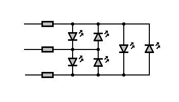
Sometimes you need more than you have. I am talking about microcontroller pins. You have to connect 6 LEDs, but you have only 3 microcontroller pins available. To use another microcontroller isn’t always a solution using decoder circuitry isn’t necessary as well.
There is a simple hint on how to do this:
Connect diodes to the microcontroller as follows:

Now, look – if you set one pin to “1” and second to “0” (leave third pin high state – as input pin), then only one led lights on. You can light two LEDs by setting the third pin as an output and state “1” or “0,” which depends on which LED you want to light.
If you need to light all LEDs simultaneously, you need to change states of microcontroller pins at some desired frequency to avoid visible blinking. Using this method, you can connect twelve LEDs using only 4 pins. This is a convenient method of expanding when using dual colour LEDs when two LEDs are packed in one case but different directions.
There is an example of AVR-GCC C code on how to control LEDs. LEDs were connected to Atmega microcontroller PB.0 – PB.2 pins.
Control function fragment:
unsigned char leds;           // Bits are the leds states
void LEDs_refresh(void)
{
static unsigned char state;   // Current refresh state
OFF();                      // Turn all pins to High-Z
switch (state)
{
default:
CLR_0();                  // Turn pin 0 low
if (leds &  1) {SET_1();} // Turn pin 1 high for led 1
if (leds &  2) {SET_2();} // Turn pin 2 high for led 2
state=1;                  // Next state
break;
case 1:
CLR_1();                  // Turn pin 1 low
if (leds &  4) {SET_0();} // Turn pin 0 high for led 3
if (leds &  8 ) {SET_2();} // Turn pin 2 high for led 4
state=2;                  // Next state
break;
case 2:
CLR_2();                  // Turn pin 2 low
if (leds & 16) {SET_0();} // Turn pin 0 high for led 5
if (leds & 32) {SET_1();} // Turn pin 1 high for led 6
state=0;                  // Next state
break;
}
}
Call this function at the frequency when blinking of LEDs is not visible. It is better to use the timer interrupt.


There could also be a further improvement of this scheme by using dual-color (red/green) LEDs instead of each of the reverse-direction pair of “normal” LEDs. In this case you could alternate pulses to the LEDs and, thanks to our persistence of vision, you can add a third color – yellow – as yet another indicator.
So, in a sense, you would create 9 possible states of indication: 3 LEDs, each capable of showing 3 different colors.