
Design and Implementation of 7-Segments-Board 1.0 – An Extension Module for Embedded System Prototype
Introduction
When developing embedded systems, it would be helpful if we could have a module for monitoring purposes. For instance, let say that your system has to process data streams. In the testing and verification step, we need to compare each input and output bytes to verify that your system is doing right. Having a monitor module is surely a great help for engineers.
Some development board has monitor module integrated, such as Altera UP1X FPGA Development Board. Inspired by its usage and benefit of such a monitor, 7-Segments-Board 1.0 is designed as an extension module for embedded system prototypes.
Description
7-Segments-Board 1.0 is a low-cost, low-power MCU extension module for monitoring purposes. It aims to help engineers doing the firmware testing and debugging on hardware prototypes. For those who build microcontroller prototype devices from scratch and do not have access to sophisticated debugging instruments, using this module would make the testing and verification process less painful. 7-Segments-Board 1.0 is designed for an 8-bit microcontroller system.
Module Specifications
The module specifications are as follows:
- Input: General purpose push-button (PB) switches (dry contact).
- Output: Seven-segments LED to display 8-bit data in hex format at a minimum.
- Low power consumption. Driving LED continuously consumes much amount of power. So it is desirable to minimize power loss in limiting resistors.
- Minimum port usage. 7-Segments-Board 1.0 is designed to work well with minimum I/O pin resources, as I/O ports are strictly limited in a common embedded system.
Block Diagram
Figure 4.1 shows the block diagram of 7-Segments-Board 1.0. In general, the module consists of decoders, LED drivers, 7-segments LED display, serial-in parallel-out (SIPO), and PB switches.
We only allocated 1 MCU Port (8 pins + 2 power lines) for module interfacing. SIPO is used to minimize port pins. The minimum total number of pins for driving SIPO is 3 pins only.
To drive a 7-segments LED display with small power, the decoder and SIPO work together to multiplex the display. It takes an input signal frequency of 20-25 Hz (i.e., 40-50 ms period) at minimum to flash the display on and off so that human eyes don’t see the flicker. The number of 7-segments display depends on MCU I/O port availability, and it sizes up the decoder as well. In this module, two 2-digit-in-1-package of 7-segments LED components are used. It means this module can display 4 digits at once. Therefore 2-to-4 decoder is used. The total number of pins for the decoder is 2 pins.
PB switches are integrated into the module for any purpose, such as to switch the display from one mode to another. The rest pin available (3 pins) is used for these switches.

Tools
Primary tools used for design and implementation of 7-Segment-Board 1.0 are as follows:
- Hardware
- AVR ISP Development Board (designed by Erwin)
- Atmel ATmega8535
- Software
- Altium Design Explorer Version 7.2.85
- WinAVR 20050214
Schematic Capture
See schematic file (SevenSeg_Sch_04172006.SchDoc) in the attached zip file. Notice that Output Enable pin (N_OE) and Master Reset pin (N_MR) are tied to VCC and GND. Therefore the total number of pinto control SIPO is reduced from 5 pins to 3 pins.
PCB Layout Capture
See PCB file (SevenSeg_Pcb_04182006.SchDoc) in the attached zip file. Note that the physical board is implemented using a 2-layer PCB with a through-hole. Figure 2 is the picture of the physical board.


Tabel 1. The List of Primary Components
| Component Name | Units | Notes |
| 2-digit-in-1-package 7-segments LED | 2 | Display units |
| 74HCT595 | 1 | 3-States SIPO Buffer |
| 74HC139 | 1 | 2-to-4 Decoder |
| 2N2907 | 4 | PNP LED driver |
| PB Switch | 3 | General purpose |
| C 100nF Ceramic | 2 | Decoupling C |
| R220 1/2W | 8 | LED current limiting R |
| R10K 1/2W | 8 | LED driver bias circuit |
| R1K 1/2W | 3 | Pull up R for switches |
Firmware Design
This project uses the Atmel AVR family microcontroller for driver implementation. No particular reason but tools availability that makes the decision. The module driver, written in C, consists of 4 separate files to simplify the maintenance: main.c, port.h, sevenseg_drv.c, and sevenseg_drv.h. The main.c file is the main program that is used to test and verify the driver. The port.h and sevenseg_drv.h files are self-explanatory. The sevenseg_drv.c contents 3 functions that do display multiplexing, that is:
void init_sevenseg(void)
This function initiates the data direction register (DDRx) and Data Register (PORTx) of AVR ports. PORTA is used for module interfacing, and PORTC is used for debugging purposes.
void send_data(uint8_t data)
It sends 8-bits data in the MCU register serially to SIPO. Each bit is transmitted consecutively from MSB to LSB along with clock signals (SHCLK, STCLK). SHCLK is used to shift bit serially, and STCLK is used to pass the shifted data into the SIPO output register. Data can only be seen at the SIPO output register after SIPO receives STCLK pulse. Thus it takes 8 pulses of SHCLK and 1 pulse of STCLK to transmit 8-bit data from MCU to SIPO.
void mx_display(uint8_t MSD1,uint8_t LSD1,uint8_t MSD0,uint8_t LSD0)
This function is responsible for multiplexing display digits. Each digit is named and coded after its position. As seen in Figure1, from right to left, MSD1, LSD1, MSD0, and LSD0 is coded 0, 1, 2, and 3, respectively. When this function is called, each digit would be flashed (based on the parameters entered) one by one from code 0 to code 3. Three main steps are used as follows:
- It selects which digit is activated by controlling the decoder.
- Then the program sends the parameter to SIPO by function send_data(uint8_t data).
- After a short delay, the program erases the displayed digit before it activates the next digit, so the next digit to come doesn’t shadow the last active digit.
The steps above is repeated after all digit are flashed.
Testing and Verification
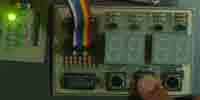
To do testing and verification, a simple program was made in main.c file. A LED board is used in PORTC as debugging tools. Program first initializes module and supporting peripheral. Figure 9.1 shows that each point of available digits would be lighted after program finishes the process. LED board would shows 0x7E.
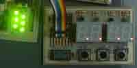
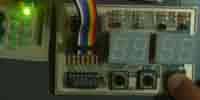
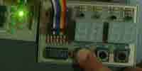
Then it would detect the press of one of three integrated PB switches. If SW1 is pressed, the LED board will show 0x01, and none is displayed on the module (Figure 3.a). The module would display number “0123” after SW1 is released (Figure 3.b).
When SW2 is pressed LED board would show 0x02 (Figure 4.a) and module would display “4567” (Figure 4.b).

If SW3 is pressed, the LED board will show 0x03 (Figure 5.a), and the module would display “89ab” (Figure 5.b). If no switch is pressed, the LED board will show 0x7E, and the module would display the last number.
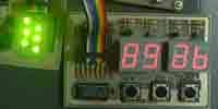
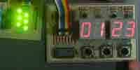
Doing multiplexing influences the brightness of the display. Figure 6 shows the brightness of the display in a dark room. When the surrounding is dark, we can easily see the display, but in a bright, the display is not as contrast as it is in the dark place. The reading is even more difficult with sunlight. Note that the number “1” seems to be brighter than the others, which means greater current flows through digit LSD0. The possible cause is the PNP LED drivers are not all identical.

Portability
The source can be translated to other MCU (8051, PIC) with minor modification.
Conclusion
From this project, we can conclude several points as follows:
- Multiplexing display is less bright than continuous display, but the power loss is reduced.
- By multiplexing the display in frequency greater than 25Hz, we can avoid our eyes seeing the flickering display.
Advices
To improve 7-Segments-Board 1.0, it is recommended to lower the value of current limiting resistors of the display to less than 220 ohms.
References
- 74HC/HCT139 Dual 2-to-4 line Decoder/Demultiplexer – datasheet. Philips Semiconductors. September 1993
- 2N2907 PNP General Purpose Amplifiers and Switches – datasheet. SGS-Thomson Microelectronics. November 1997
- 74HC/HCT595 8-bit serial-in/serial or parallel-out shift register with output latches; 3-state – datasheet. Philips Semiconductors. June 1998
By: Ivan Christian and Erwin
Because of database crash Latest comments were lost. I am rewriting the link to project schematic.
Schematic
If there is anything else needed or missing just let me know.