
Finally, some updates on the AVR DDS3 signal generator. The circuit is practically done, and PCBs are made.
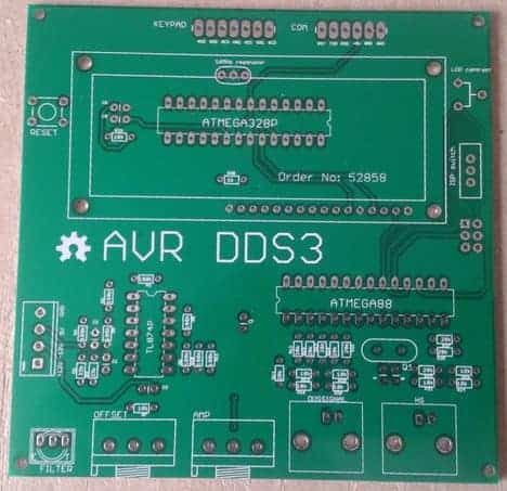
I decided to go with two microcontrollers on board to make it more functional. One microcontroller, Atmega328P, is gonna be dedicated to user interface and signal generator control. The second Atmega88 is gonna be used for signal generators only. This will give un-interruptable signal output while changing parameters or simply doing signal sweeps.
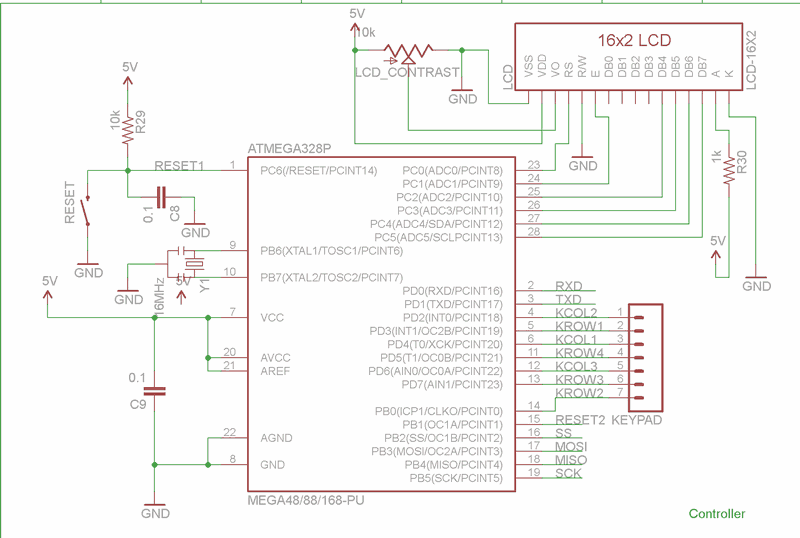
A simple keypad should be convenient for entering frequency values and menu navigation.

Maybe this isn’t the best choice, but this is what I had on a desk and wanted to put it to use. If I find it annoying and there will be more bugs or more flaws, the schematic will be remade.
I decided to add a computer interface. So there is a UART connector that suits SparkFun’s FTDI Basic Breakout board.

There is not much change in the DDS generator since the last projects. There is the same R2R resistor ladder DAC used, which is a simple and cheap solution. I have used the Atmega88 microcontroller here, which has 8KB of Flash, 1KB of SRAM.

I haven’t decided yet, but all signal data will probably be stored inside the controller chip and uploaded to DDS microcontroller SRAM using the SPI interface. This will be easier to upload new signals using a PC. And finally analog part. This is the same circuit that was modeled in this previous post.
Here is a first mistake in a board. If you intend to use Arduino bootloader – it wont work as I put reset line directly to USART port. This is how it should be:

I love to test this circuit. It’s possible to downlload?
Here you go.
https://scienceprog.com/wp-content/uploads/2012/07/eagle3_2.zip
I’m gonna focus on firmware now. After this I will probably fine tune circuit by fixing small issues and changing several footprints. Layout also needs some shifting around. Your comments on this are also welcome.
Since I’ve got 10 PCB boards from seedstudio, I’ll be giving few away. Cannot sell them as they have issues. Will let you know giveaway conditions pretty soon. Thanks
Oh, please send one board to me.
So started to do simple testing of board and found another rude mistake. Filter feedback OPamp pins are not connected. It has to be fixed with jumper wire.
Another issue – filter bypass switch should be connected in opposite way. Filter output should be open when disconnected instead of shorting it.
R5 resistor should be 33.33k instead of 100k. C2 should be 18p instead of 33p
Run simple demo signal on Atmega88. It seems that TL074 is a bit slow for square signals. There are overshoots and ringing on sudden signal rise. Probably faster opamp could solve this problem. Square signals can bee smoothed smoothed using filter. other signals that rise gradually look great. I’ll make a separate post with all fixes and signal samples soon.
Alex, got your posting address – will send board soon.
Anyone else who wants a PCB to play around – please leave decent comment with thoughts and suggestions here or in other AVR DDS3 posts and then ask for board by sending your mailing address using contact form (https://scienceprog.com/contact-form/)
There are 7 PCBs left.
Hi, I just saw your project which is amazing and it is so nice that you could share your design. I am working on a similar project about waveform generator. At first I am going to use MAX038 which is not produced anymore. And your design helps a lot. I want to know what is the maximum frequency it could get. In my project, this generator works as a modulator. So I really care about the highest frequency it could get. Thank you again!
hello, i would like to receive one board as well so I can upgrade my DDS2 that i’ve built some time ago. its a really nice tool for my workbench.
thanks and keep doing this great project.
Gustavo
Hello!
Very pleased to see such a good design, Look at the label on the PCB package like the Chinese text, I want to produce from our Chinese, I will continue to focus on the project after you optimize, thanks for sharing! !
Hi,
interesting project, thinking of making one, but need to mahe a pcb for it.
Good job. Thanks for sharing. Is the outbut bipolar or not, I couldnt understand, can u help me? I need a waveform generator with adjustable amplitude bipolar output.