
Finally, the second version of the improved AVR DDS signal generator is here. THE first AVR DDS V1.0 generator was only an attempt to run the DDS algorithm without any analog amplitude control. In this DDS generator version, I still wanted to keep things as simple as possible using a minimum count of widely available components in the updated circuit. Also, I kept a single-sided PCB approach.

AVR DDS specification
AVR DDS signal generator V2.0 is a firmware-based DDS signal generator that uses a slightly modified Jesper’s mini DDS algorithm adapted to AVR-GCC C code as in-line ASM.
The AVR DDS signal generator has two outputs – one for DDS signal and another for high speed [1, 8MHz] square signal – which may be used to bring back to life microcontrollers with wrong fuse settings for other purposes where a high-speed square signal may be needed. A high-speed (HS) signal is output directly from the Atmega16 OC1A(PD5) pin.
The DDS output is used for all complex signals generated via the R2R resistor network and is adjusted via LM358N offset and amplitude regulating circuits. Two potentiometers can control offset and amplitude.
The offset can be controlled in range +5V..-5V while magnitude in range 0..10V.
DDS frequency range is from 0 to 65534Hz which is more than enough for testing audio circuits and other purposes.
Main AVR DDS V2.0 signal generator features:
- A simple circuit with easily accessible and cheap components;
- Single-sided PCB;
- In a box power supply with an external AC plug;
- Dedicated high speed (HS) signal output up to 8MHz;
- DDS signal with variable amplitude and offset;
- DDS signals: sine, square, saw, rev saw, triangle, ECG, and noise.
- 2×16 LCD menu;
- Intuitive five-button keypad.
- Frequency adjusting steps: 1, 10, 100, 1000, 10000Hz;
- Restoring the last configuration after power-up.
In the block diagram, you may see the logical structure of signal generatorV2.0
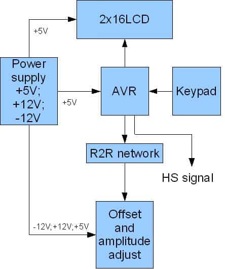
The power supply for the AVR DDS signal generator
As you can see device requires several power supply voltages: +5V, -12V, +12V, and GND. The -12V and +12V are used for offset and amplitude control. The power supply is constructed using a simple transformer and a few linear voltage regulators such as 7812, 7805, and 7912.

The power supply block is assembled on a separate prototyping PCB board.
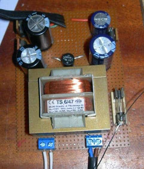
If you do not want to build a power supply, you may use a PC ATX power supply unit where all required voltages are available. You may need to modify Molex connector wiring as follows:

DDS Generator control with LCD menu
All DDS generator actions can be viewed in the LCD menu. The menu is controlled with five buttons that are next to the LCD module
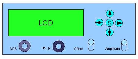
Up and Down arrow buttons are used to browse the menu, while Right and Left arrow buttons are used to change the frequency value. When the middle button is pressed – the DDS signal is started. Press the middle button again to STOP the signal generator.

It is essential to notice that there is a separate menu item for changing the frequency step. This functionality is convenient if you need to change generator frequencies in a broader range with fewer button clicks.
The noise generation feature doesn’t have a frequency setting. It uses a simple rand() function where results are continuously sent to DDS output.
The high-speed signal has four frequencies available: 1, 2, 4, and 8MHz.
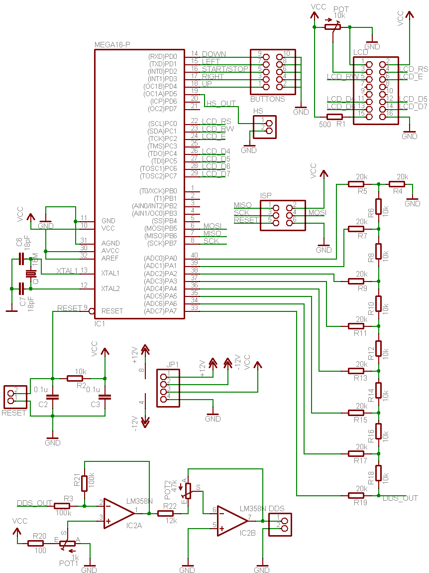
The circuit diagram and PCB
The circuit diagram of the AVR DDS generator (without power supply) is straightforward with widely available components. It uses the following building parts:
- AVR Atmega16 microcontroller clocked with 16MHz external crystal;
- Standard HD44780-based 2×16 LCD module;
- R2R DAC is made of simple resistors;
- LM358N – a low power dual op amplifier;
- Two potentiometers;
- Five buttons;
- several connectors and sockets.
The circuit diagram
Single sided PCB:

Assembly of AVR DDS signal generator
DDS generator prototype is assembled into the plastic box. The most significant part of the enclosure is taken by the Power supply. You could make the end device much smaller if you used an external power supply.
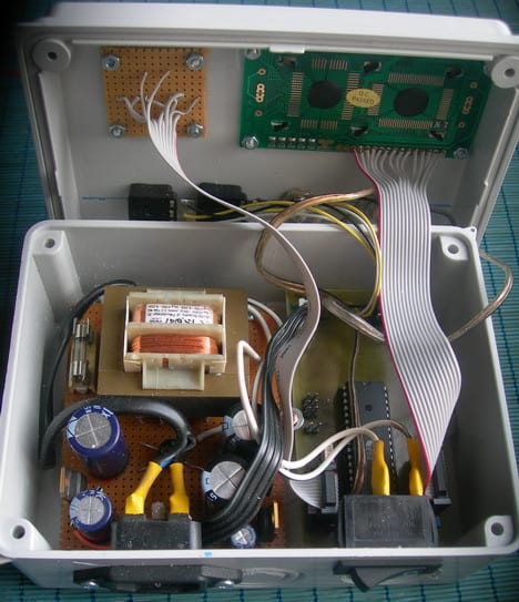
Last test run of the DDS generator before closing the box:
Programming AVR DDS 2.0 Firmware
As I have mentioned before, the DDS function is a modified Jesper’s DDS algorithm. The main modification of the code is adding the ASM line, which enables to stop of DDS generation at any time. Earlier, the only option was to reset the device to have it finished.
Now, the Signal_Out routine checks if the CPHA bit is set in the SPCR register, which is set during the external interrupt service routine (when the stop button is pressed). DDS generating algorithm takes 10 CPU cycles instead of 9 without a stop feature.
void static inline Signal_OUT(const uint8_t *signal, uint8_t ad2, uint8_t ad1, uint8_t ad0){
asm volatile( "eor r18, r18 ;r18<-0" "\n\t"
"eor r19, r19 ;r19<-0" "\n\t"
"1:" "\n\t"
"add r18, %0 ;1 cycle" "\n\t"
"adc r19, %1 ;1 cycle" "\n\t"
"adc %A3, %2 ;1 cycle" "\n\t"
"lpm ;3 cycles" "\n\t"
"out %4, __tmp_reg__ ;1 cycle" "\n\t"
"sbis %5, 2 ;1 cycle if no skip" "\n\t"
"rjmp 1b ;2 cycles. Total 10 cycles" "\n\t"
:
:"r" (ad0),"r" (ad1),"r" (ad2),"e" (signal),"I" (_SFR_IO_ADDR(PORTA)), "I" (_SFR_IO_ADDR(SPCR))
:"r18", "r19"
);}
The signal generator function code reads signal values from the look-up tables that are stored in flash memory. They need to be flashed into specific sections where the address starts with 0xXX00. These sections for every signal have to be defined in the makefile for proper memory arrangement:
#Define sections where to store signal tables
LDFLAGS += -Wl,-section-start=.MySection1=0x3A00
LDFLAGS += -Wl,-section-start=.MySection2=0x3B00
LDFLAGS += -Wl,-section-start=.MySection3=0x3C00
LDFLAGS += -Wl,-section-start=.MySection4=0x3D00
LDFLAGS += -Wl,-section-start=.MySection5=0x3E00
LDFLAGS += -Wl,-section-start=.MySection6=0x3F00
The LCD control library is described here.
The source code is commented pretty well, and if there will be any questions or suggestions, please drop a comment.
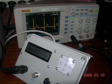
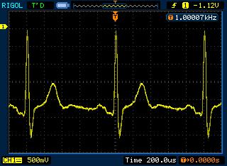
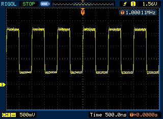
Testing DDS signal generator
I have tested the signal generator with an oscilloscope and frequency counter. Signals look reasonably good in all frequency range [1 to 65535Hz]. Amplitude and offset regulator responds well with some limitations. For instance, if the offset is set to 5V, then a maximum of visible signal amplitude may be adjusted to 5V as the rest of 5V is already used for offset (same as if the offset is -5V).
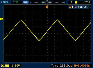
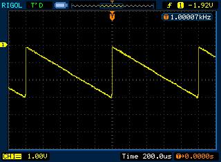
Here are a few test signals shots from the oscilloscope screen:


Future updates could include sinus sweep functionality. Because of the limited capabilities of a small microcontroller, this is still a work in progress.
Download the latest firmware (WinAVR20071221) and source code version here (source code and hex [120kB])
Download the EagleCAD schematic and PCB here ( EagleCAD project[45kB])
Proteus simulation files with the latest firmware included (avrdds_proteus [31kB])
See also how talent management is important in business.
Excelent project. I wondered thought if others might be interested in my way of making custom “membrane” switches for projects?
Design the artwork and print it out on a sheet of paper. Cut it out the correct size and put it in the middle of a laminate pouch and run it through the laminator. Mine is not a very good laminator, so I actually run it through again as soon as it comes out.
Cut out the box and cut the laminated sheet to be at least 10mm larger than the hole. Run hot-melt adhesive around the hole inside the BOX. Place box face-down on a hard surface and place your laminated legend(s) in place. Quickly place a piece of polythene over that and a heavy object to flatten it all while the glue sets.
using a sharp knife carefully scrape away any hot-melt adhesive that ouzed out onto the face of your legends while cooling.
Mount the switches onto their own PCB or any inflexible surface and mount them behind the legend, fixing the edge of the board via spacers/washers to the box. the switches should be pressed into the legend just slightly when monuted.
Which fuse-bits is this Atmega16 using??
Fuse settings with PonyProg
Thankyou for the great tutorial on you signal gen. I was wondering, would you possibly be able to write your DDS algorithm in pseudo code? I am a PIC guy, and all that AVR assembly is driving me nuts 🙁 .
Thankyou greatly
krazatchu made PCB modifications in order to get rid of smd. Also he made following modifications:
1) added the power supply to the board to run from battery…
2) removed the ISP to save space
3) changed the pin header for lcd to 1×16
4) fat traces for toner transfer…
5) separate ground returns for analog and digital…
Just follow forum thread
http://forum.scienceprog.com/viewtopic.php?f=9&t=281&p=399#p399
So if you like printer toner transfer pcb technology, you can choose this option.
It will be very interesting when we can get our hands onto Xmega chips with the streaming DMA DACs, and what kind of DDS we can cook up then.
I’ve assembled V2.0 DDS generator.
It doesn’t work:
1) LCD display without any character. There are black rectangles in the upper line only.
2) There is not any pulse at PC0…PC7 outputs (found by oscilloscope)
Several times I did READ and WRITE operations. So MEGA16 is in good condition.
It might be FUSE bits are not O.K.
Here are the latest FUSE bits, which I got from the chip:
Fuses
OSCCAL = B1, B1, AC, AF
BODLEVEL = 0
BODEN = 1
SUT = 2
CKSEL = E
BLB1 = 3
BLB0 = 3
OCDEN = 1
JTAGEN = 0
CKOPT = 0
EESAVE = 1
BOOTSZ = 0
BOOTRST = 1
Would you please give me advice how to solve this problem?
It is hard to say now. Above you can see fuse settings done with PonyProg software. According to your settings seems to be that CKSEL is wrong. Should be CKSEL=F.
I tried CKSEL=F also, but with the same result.
I used another ISP programmer. I used it many times for many different projects.
Would you please answer to my E-mail directly
Can you add in software duty cycle??Wich compiler you use??
Compiler is WinAVR AVR-GCC.
Adding duty cycle would be a little bit complicated. Probably best solution would be to use HS output and change duty cycle by changing timer output compare parameter. Right now I am not planing on adding this functionality. But you are free to modify the code.
Hello,
thanks for this interesting project, but i have the same problem as Anatoliy, it wont start, black rectangles on LCD. It is not mt first AVR or/and PIC project, so i am confused, what I do wrong? I use serial COM port programmer and PonyProg software with fuses as in picture in this thread. Any ideas and help please? 🙂
Thank You in advance!
It started working, i just didnt write right fuse settings with PonyProg (how typical 🙂 ).
Hi
what type of complier did you used?
For PonyProg selected fuse:OCDEN, BOOTSE1 and BOOTSE0.Now my DDS work…73!
Ok…
I keep getting a non-working atmega16 (LCD top row lit only). I am using STK500 with AVR Studio 4 to program the atmega16. I would guess that it’s not working because of the fuse settings. Can someone who used AVR Studio successfully make a screen shot of the fuse settings please.
Also, with the osc fuse, should it be set to one of the “ext crystal” settings, because the schematic uses a crystal with 18pf caps.
PS… This is probably a stupid question but I should be programing the FLASH right? With AVR Studio you can program the FLASH and/or EEPROM.
i simulate this function generator with proteus 7.2; the result is:
lcd and lm358 and noise signal all are okey but sin and other pulses are not generated…
any idea plz???!!!
I just tried – it simulates ok. I have attached latest Proteus simulation file to the end of article.
can the same project be done using atmega16L.WH ALL D CHANGES TO BE MADE with this regard…hlp me
first of all thx scienceprog for reply and upload new files. and could you please say wich version of proteus you use for test the FG_DDS_2? i run it with 7.2 and same result applied.
Now i finish testing the DDS_2 on BreadBoard… the result is:
all pulses are generated. my fuse bits that are zero (Marked) are: BOOTSZ0 & BOOTSZ1 & SUT1 & SUT1 at Hattel Paralel Programer.
The problem is lcd and maximum Frequancy, lcd after start will dissapear and Fmax=20KHz
are fuses and my lcd okey??
any idea plz…???!!!
I used Proteus 7.2.
I cannot predict how it runs on 20MHz as I only tried on 16Mz. If you have possibility – try change it to 16 to see how it works. Anyway all timings are tied to 16MHz crystal, so menu functions will be incorrect.
Hi,two questions,here is a main.eep,do I need to program it into atmega16?second,I use ponyprog and stk200 cable and fuse settings from above to burn the atmega16,I also get the result on top row of the lcd with squares only,I tried various combinations of fuse setting still with no luck,and now I got two dead atmega16 after many attempt of fuse settings.can please someone guide me the right way to program the atmega16.
Hello!
Great project! I have made pcb with little different pin connection. I looked into source and made some little changes:
in main.c
#define R2RPORT PORTD
#define R2RDDR DDRD
//define button port and dedicated pins
#define BPORT PORTC
#define BPIN PINC
#define BDDR DDRC
#define DOWN 0//PORTD
#define LEFT 1//PORTD
#define START 2//PORTD
#define RIGHT 3//PORTD
#define UP 4//PORTD
//Define Highs Speed (HS) signal output
#define HSDDR DDRC
#define HSPORT PORTC
in lcd.h
#define LCD_RS 5
#define LCD_RW 6
#define LCD_E 4
#define LCD_D0 0
#define LCD_D1 1
#define LCD_D2 3
#define LCD_D3 4
#define LCD_D4 0
#define LCD_D5 1
#define LCD_D6 2
#define LCD_D7 3
#define LDP PORTB
#define LCP PORTB
#define LDDR DDRB
#define LCDR DDRB
Whis changes describes my schematics connection. I use avr-gcc (WinAVR 20090313) 4.3.2 to complile the code. Everything is fine. But the i try to test it in Proteus model (i also changed it correcpondly my schematic) nothing works. Can you give some idea? I can send all sources if you need.
In “AVR controlled DDS generator software writing” post you wrote that
loop taking 10 clock cycles was able to reach 6.25kHz.
Here we have 256 samples, 9 clock loop and same 16mHz clock… and
frequency over 65kHz.
Counting other way… On 16MHz clock and 256 samples we can get 62.5kHz
if we put sample out every clock cycle. But the loop is 9 clock cycles.
So the question is: If the loop puts a sample out every 9 clock cycles
the “real” frequency where all samples are going out is ~6.9kHz and
above that this DDS algorithm is skipping samples, yes?
Ups, my bad 🙂 I’ve pasted this comment under new version with 10 clock cycles loop, but I thing everyone gets the idea.
to mako…Delays are at least in milliseconds, so there should be no prob with that. if you have a chance – test your hardware with another application, to see if there is no bugs in board.
———–
to johny126…when frequencies goes over 6.9kHz – algorithm starts skipping samples – this way loosing resolution. So you can increase frequency as long as you are satisfied with signal shape.
Hi,
dear Scienceprog,
I´ve been trying to set this project, for a while ;(
with some problems in the LCD
did your project for win avr lcd 4 n 8 bits
and doesnt work either,
so i guess is a problem with the LCD
here , in this dds2 I used this fuses in avr studio, from what you show in pony prog:
high 0x19, low 0xcf,
lock bits, 0xff
no response, just a blank line,
in this project and the 8 n 4 bits
could it be the delay? (some one told me need 400us)
where can i set this in your libraries, thanks
😉
Hi scienceprog.
i found my mistakes. (fuses)
i used 2*ca3140 for final op-amps insted of one lm358 because of its higher slew rate. and i realize that its better to parallel a 70pF cap on DDS_OUT to reduce the output noise.
sorry for my english. (im Iranian)
regard. post comment if idea.
Hi and thank you for your nice project,
I have built my version of DDS replacing Smd parts and made it on pcb. For the programming I used AVR Studio in conjuction with WinAVR but all I get is 16 blank chars on LCD. Used osciloscope/multimeter to test output etc and 2 more mega16 but nothing changed.Fuse setting were calculated to 0x19 0xC9 if I can recall based on your ponyprog screenshot.
Any ideas?
Thanks in advance!
To everflow:
I programming Atmega with AVRStudio but not needed select JTAGEN. The fuse settings: HIGH=0x59 and LOW=0xCF. I use this settings and working the DDS.
To san398:
Many thanks for your reply. It did work! If I enable JTAGEN it just fails! Would be nice to figure out what’s wrong there but that would do for now. Thank you again you I was busting my mind many days over now with that fuse thingie.
Anyone has used a DAC instead of the R2R network?
I am thinking of using a AD558. Do you think it’ll work? I haven’t got into DACs so far and I don’t rly know if that one will be a direct replacement for the ladder network so any ideas are welcome.
Thanks!
Should work perfectly in my opinion. Just connect CE and CS pins of AD558 to “ground” to enable “transparent” mode.
Nice project! Could it be modified so that the phase of the waveform can be adjusted?
Great job! I using WinAVR 20090313, and with the ‘s’ opimizations, I needed to change this code to make it work.
struct signal{
volatile uint8_t mode; //signal
volatile uint8_t fr1; //Frequency [0..7]
volatile uint8_t fr2; //Frequency [8..15]
volatile uint8_t fr3; //Frequency [16..31]
volatile uint32_t freq; //frequency value
volatile uint8_t flag; //if “0”generator is OFF, “1” – ON
volatile uint32_t acc; //accumulator
volatile uint8_t ON;
volatile uint8_t HSfreq; //high speed frequency [1…4Mhz]
volatile uint32_t deltafreq; //frequency step value
}SG;
It works as published when the optimization level is set to 0.
Thanks!
Hello,
I have a problem with this project. It seems it operates at twice the speed. On HS output, measuring with an frequincy meter, for 1Mhz i get 2Mhz, for 2Mhz i get a reading of 4Mhz, etc. Also, the menu seems to work too fast, if i pres a button once (for a short period of time) it will repet the command (it will switch verry fast, something like double pressing).
The uC was programed using the firmware from: https://scienceprog.com/wp-content/uploads/2008/03/firmware.zip .
The PCB is the one from this site, the only modifications i’ve done are: removed ISP connector and rearenged the components to fit BNC connector directly to PCB.
Xtal is 16Mhz with 22pico capacitors.
Thanks.
That is really strange. Did you try to re-flash chip? What about DDS signals – are they generated correctly?
First time i’ve flashed the chip (not verry shure about the fusebits) and it worked to slow 🙂
I no not have an osciloscope to view DDS signals…
In the forum topics there are a few variants of fusebits, which one is corect? Is low fuse: 0xCF and high fuse: 0x59 corect?
Thanks!
My fuse settings are
High = 0b00011001 = 0x19
Low = 0b11001111 = 0xCF
With high fuse set to 0x19 the devices doesn’t work at all, it just shows an black row… I’m lost…
How about a firmware update? The sweep would be really nice for measuring inductors by means of resonance frequency.
It takes way too many button presses to do that manually with this signal generator.
high fuse = 0xD9
low fuse = 0xFF => the device work’s at twice the speed 🙁
Another strange thing i noticed: when set to OFF i can read 16Mhz (speed of crystal), when set to ON => twice the value it should be….
Just read the fuses from signal generator:
high fuse = 0xD9
low fuse = 0xFF
Hope this helps.
high fuse = 0xD9
low fuse = 0xFF
It work!!!
Sweep is in the list – just need time to work on it.
I have build this fine project, and its works very fine with a LCD HD44780 display, but will not work with a LCD KS0066 display. What to do ??
more about displays:
The KS0066 controller is a klone of HD44780, and should be Equivalent.The 2 displays work fine in all af my 4 other Atmel-projects, so why will the KS0066-display not work in this project??
Can someone explain ??
Hi
I’m thinking to build this project but the problem is I can’t find a HD44780 LCD. Is it ok if I use a different LCD?
Hi,i build the project,but It doesn’t work.I see only black rectangles in the first line.What that means?Bad programmed Atmega or wrong LCD.I’m using AC162B LCD( KS0066U) – same pinouts like many other models.
Thanks in advance!
Problem Fixed.Wrong programmed Atmega.Uncheck JTAGEN checkbox in Ponyprog.My settings are :
OCDEN,BOOTSZ,BOOTRST,SUT1,SUT0 checked.All others are NOT checked.No problem with KS0066U Driver!I can try with Bigger LCD module-PC2002L (same pinouts and driver).
Thanks for nice project.
73 from Bulgaria,LZ1JER.
Hi Scienceprog,
I appreciate you making this cool project available to everybody! I hope yopu are still watching this blog. Anyways, I built it and everything seems to be working fine. The LCD reads fine and the buttons work fine, but I am not getting a readable signal out of it. I get a signal of sorts, but it seems like maybe it’s just static.
Any ideas what might be causing this? I am hooking it up to my scope to try to read it.
Thanks,
Jeremy
Never mind, I got it working and it is awesome!!!! I had a short that looked like a trace, but when I compared it to the PCB I realized it wasn’t supposed to be there.
Regards,
Jeredmy
Glad you made it. And yeah… most of problems occur in hardware design – especially when when PCB is home manufactured. Solder bridges between traces and traces with micro-cracks (open) can be hardly seen at first glance.
hi, great project… i made it with two channel output and runing well but vr1 not fungction as moving phase..is it correct for moving phase,what do you mean with offset..?? i need two channel signal with diferent phase each other so i make two opamp connected to net resistor.
Is it possible to make variable freq while program generating signal? then we can change the preq without off the signal first.
Im waiting for your respons..
Thanks
-Dodi Suwardi-
I was thinking about frequency changing without stopping signal, but each new button read would reduce signal resolution. Right now there is a Sweep in To DO list. Don’t know when it will be done.
Nice project! Works fine! I’ve designed a PCB for the power supply. Look at my page http://www.martin-jacobsen.de -> Projekte -> Funktionsgenerator to get the EAGLE Files.
Ow great ….!! i can’t wait for your new version of AVR DDS , the output must be: can move a phase of sine wave, and must be change freq while run, then the device will be perfect as developer tool.
hi scienceprog, great project you done, it is very useful. i’m newbie of winavr, could you mind to tell me something in your source code, is it possible to make the waveform patterns to be variable? such as store it to the RAM or EEPROM (don’t know the speed and size are enough), then we can change the values in real time, because i plan to build a arbitrary waveform generator.
Hi!
AVR DDS2 doing great. I am very pleased. Sweep functions would be great. I thought about how I did it:
1st step: to enable a generator while the generator is in working stanje (except for future sweep mode)
2nd step: add the new mode that would have 3 parameters: the lowest frequency, highest frequency and duration (the time it takes to increase the frequency of the lowest to the highest, or that it is the duration of one step, anyway will sweep functions do increase the frequency in increments that are less default)
3rd step: to save the parameters in EEPROM
4th step: routines to be run when the generator set to “ON” state (read parameters from EEPROM, calling routine that is executed when the generator is in normal mode and when the press “Increase frequency” in the routine, now check whether the value is reached frequencies greater than or equal to the highest frequency, if not even increase the frequency, and if it is set to the lowest frequency, already check that you pressed “OFF” button)
Unfortunately, I know assembler for the PIC, so we ask the authors to make at least the 1st Step (very useful).
Another request: I also made the AVR DDS1 but does not work (bad Fuses, I think). I’ve destroyed 4 ATmega8 chips. I do not want to put a plate in the trash. Can you tell me the Fuses state for DDS1. Please hexadecimal value, because I use AVR Studio 4 for programming, like following example:
“My fuse settings are:
High = 0b00011001 = 0 × 19
Low = 0b11001111 = 0xCF ”
Thanks in advance
1st step again: to enable a generator while the generator is in working state (except for future sweep mode)
Also, I would like to share my pcb design because it is very nice and easy to reproduct (no SMD components).
How can I do this?
Thanks for sharing the project.I have one question and that is how do you calculate the ecg signal values?I can make sine and other pulses values using mathlab but do not know the formula for ecg.
thanks in advance.
Hi scienceprog,
That great project,Works fine with me! Is that posible to adjust frequency up to 10 MHz for sine wave ?
I need 10 MHz for transmitter antenna
Regards,
Irwan
No this project works up to 64kHz for sine waves, going up would reduce signal resolution significantly. If you need higher sine wave frequencies you should use specialized hardware based DDS chips.
Hi
in main.c =
//variables to control TDA7313
where is TDA7313 on the circuit diagram ?
How do I change in sine wave from 1000Hz to 50Hz
and ECG 100Hz to 80Hz ?
Hi Scienceprog, again
I am not good at C.
Is there another source code version in Arduino?
Before and without OP-AMP (LM358) signal have a good shape (i.e. sinus), but, when I insert LM358 signal shape is very poor after 5 kHz. I insert LF353 instead LM358 and signal is better but not as input signal.
Any sugestions?
hi scienceprog.I want to sorce cod vision or bas com of avrdds2.
hi all
IRANIAN DDS!
http://micro-project.blogfa.com/post-94.aspx
Hi all
i made AVR DDS 2.0, it’s great! But when i compile the source code the hex file does not function properly, i want also 100KHz as output in the High Frequency output and it’s not function, the micro runs only the original code! What i’m wrong? Please help me!!!
Hi all
i solve the problem as Geoff solved it: I modified the code into this, i’m compiling with WinAvr 20100110
struct signal{
volatile uint8_t mode; //signal
volatile uint8_t fr1; //Frequency [0..7]
volatile uint8_t fr2; //Frequency [8..15]
volatile uint8_t fr3; //Frequency [16..31]
volatile uint32_t freq; //frequency value
volatile uint8_t flag; //if “0?generator is OFF, “1? – ON
volatile uint32_t acc; //accumulator
volatile uint8_t ON;
volatile uint8_t HSfreq; //high speed frequency [1…4Mhz]
volatile uint32_t deltafreq; //frequency step value
}SG;
Fuses HIGH=0×59 and LOW=0xCF
confirmed for me too.
Check out new AVR DDS V2.0 signal generator implementation (by Vassilis Papanikolaou). http://www.electronics-lab.com/project/dds-function-generator/
It uses factory-made PCB and few mods. Looks great – greater than original.
Uploaded software and hex with corrected part:
struct signal{
volatile uint8_t mode; //signal
volatile uint8_t fr1; //Frequency [0..7]
volatile uint8_t fr2; //Frequency [8..15]
volatile uint8_t fr3; //Frequency [16..31]
volatile uint32_t freq; //frequency value
volatile uint8_t flag; //if “0?generator is OFF, “1? – ON
volatile uint32_t acc; //accumulator
volatile uint8_t ON;
volatile uint8_t HSfreq; //high speed frequency [1…4Mhz]
volatile uint32_t deltafreq; //frequency step value
}SG;
can you generate a wav voice on this
There can be stored 256 samples instead ECG.
This is just great Vassilis! Bravo 🙂
Can anybody help me.
I tried to compile new source and got the following error:
c:/winavr-20100110/bin/../lib/gcc/avr/4.3.3/../../../../avr/bin/ld.exe: section .MySection1 [0000226c -> 0000236b] overlaps section .data [0000226c -> 000023bd]
make: *** [AVRDDS21.elf] Error 1
Build failed with 1 errors and 1 warnings…
I don’t have enough experience and I don’t know where I’m wrong. Please, put pnproj file in firmware.zip or give me some other advice.
I will try to implement sweep function in firmware.
Tihomir Benko.
Have a great change in the software project? 25-11-2010 ….
Hi there… Great project… Thanks… My device have been not work, till i disable JTAGEN. My fuses for AVR910 and CodeVisionAVR: OCDEN=0, BOOTSZ1=0, BOOTSZ0=0, SUT1=0, SUT0=0. With JTAGEN=0 device not work. Maybe i’ll help somebody by this information.
HELLO
Can someone help me?
DDS2 documents there is a mistake!
TihomirBenko
me the problem was written by
Description Resource Path Location Type
make: *** [Firmware.elf] Error 1 Firmware C/C++ Problem
Description Resource Path Location Type
section .MySection1 [00003d68 -> 00003e67] overlaps section .data [00003d68 -> 00003eb9] Firmware C/C++ Problem
HELLO
Do not have the problems listed above will help a person?
Makedon,
I don’t solve problem with compile (Overlaps section…). Sorry.
Tih.
Hi to all and a happy new 2011….
Is there any NEW firmware like my download
today?
Version 2.0
I wont do prog. the Atmega16XX
thx for help in use
Dirk
Hi to all,
Is it possible to extend resolution to 0.1 Hz?
Any suggestions?
Thanx
Hi@all,
can someone compile this code for Mega32?
Same pinout and fuse settings.
THX
As it is easy to do I have compiled source for Atmega32. Download it here:
https://scienceprog.com/wp-content/uploads/2008/03/FirmwareM32.zip
Cheers
Hi!
Is it possible to use compile this for ATmega324P? The pins used are the same for the mega16 and the mega324p.
Thanks!
I sugest to repleace LM358N ->>> OPA2134
you see 30kHz square wave like your 1kHz
The problem with “section .MySection1 overlaps section .data” is probably seen in new AVRStudio.
I had the same problem in AVRStudio 4.13 SP2, build 571.
I had the same problem. It looks, that now the data sections in the program memory have to be defined in a different way.
I have changed the data section definitions from this:
const uint8_t sinewave[] __attribute__ ((section (“.MySection1”)))=
to that:
static const char sinewave[] PROGMEM =
and then the table containing pointers has been changed from:
const uint8_t *SIGNALS[] ={
sinewave,
squarewave,
trianglewave,
sawtoothwave,
rewsawtoothwave,
ECG
};
to this:
const char *SIGNALS[] ={
(prog_char*)sinewave,
(prog_char*)squarewave,
(prog_char*)trianglewave,
(prog_char*)sawtoothwave,
(prog_char*)rewsawtoothwave,
(prog_char*)ECG
};
Additionally, because I have changed data type from ‘uint8_t’ to ‘char’, the declaration of function using it has been changed from:
void static inline Signal_OUT(const uint8_t *, uint8_t, uint8_t, uint8_t);
to:
void static inline Signal_OUT(const char *, uint8_t, uint8_t, uint8_t);
Now it compiles with 0 errors/warnings.
Here is the complete ‘main.c’ corrected for new AVRStudio versions to avoid the “section .MySection1 overlaps section .data” issue:
http://mysiaki.dyndns.org/WRZUTA/main.c
Regards,
P.
All,
Please forget my previous posts.
Source was compilling, but I have noticed that lower portions of waves were corrupted.
Finally I have found, that the “Section overlaps” issue appears because the location of the .MySection x was not defined.
This is probably because you did not include the Makefile to the project.
To force the AVR Studio to use the Makefile (and thus to point the section addresses) do:
Project -> Configuration Options -> General -> Use External Makefile
Point to the Makefile on the disk.
Make sure, that the Makefile content is correct – the MCU type, the target filename and so on.
I have checked – now it works correctly with the original source code.
P.
I made this divice but i have a problem. i programmed atmega16 using ponyprog, when i power up the divice on lcd are displaied 16 black squares. i connect my osciloscope to the output and press start and it works perfect but lcd remaines black
Hi, Works very fine. Y do it!!! thankyou.
I miss PWM, can you do it?
exelent work!
thanks again!!
hey: “October 28th, 2010 at 7:26 pm ”
German Sir
yes i reverse engineering, But why did you Sad?!
i just gave it little changed (my source have duty cycle and keypad):
http://micro-project.blogfa.com/post-94.aspx
I said help from foreign website
Soon I will update it for better and Generate more frequency
And place them for you
I hope you happy
bye
Is there can be used HD44780 based LCD? Where can I find more documantation and source codes?
sir
i am do this project but one problem is their frecuancy does not match with cro & disply per 1000 hz ,300 hz less compare to cro what is problem in this
Sir,i kindly request you solve this problem
Con. No. 9730939336
kumar, could you be more specific about the problem.
I have the same problem as above, for example when i set the micro to 2500hz I only see about 150hz on the osilloscope, and adding 100hz to my my dds output only gives about 10hz increase on the ossiloscope,—–I have also another question: on the proteus stimulation file in here 741 opamp is used but on the shematic of circuit (the jpg file) lm358n is used, which one is better to use and what are the differences? thanx
to valantis:
your problem is because of the jtagn fusebit:
1- read the fuse bits on your atmega16
2- change the value of Jtagen fusebit to “1”.
3 write the fusebits to your atmega16.
you will have your lcd working fine!
if the value of Jtagen fusebit was already 1 then I guess you have problems either with you circuit or the contrast POT and connections to your lcd.
and all three Cclock fuse bits should be inactive since we are using external crystal in high range.
Thx pklawit!
I will try to compile source and I hope to improve sw for automatic increase frequency (sweep).
Tihomir Benko.
Hi all,
TO solve the “section .MySection1 [00003d68 -> 00003e67] overlaps section …” problem, the other solution is to add the linker options in AVR Studio v4.18.
You can add it in Project>Configuration options>Custom options.
Click the [Linker Options] in the “Custom Compilation Options” and find the EditBox on the left side of the “Add” button, copy the following lines one by one and press “Add” button for each line. Press the “Ok” button and you are done.
-Wl,-section-start=.MySection1=0x3A00
-Wl,-section-start=.MySection2=0x3B00
-Wl,-section-start=.MySection3=0x3C00
-Wl,-section-start=.MySection4=0x3D00
-Wl,-section-start=.MySection5=0x3E00
-Wl,-section-start=.MySection6=0x3F00
Thank’s for the nice device!
I replicated this generator, it’s working perfectly.
I had a problem with fuse bits.
I used PonyProg with simple COM-port programmator.
I didn’t use bit JTAGEN, leave it unchecked (empty). It resolved problem with bits.
Good evening,
I intend to do my own pcb, and i whant to know if i can mirrored lcd pin connection on mcu and how.
Good day,
If i reverse order of connecting the LCD pin to mcu , what changes i need to do in software to work.
I try but with no result.
To can put the lcd on top side i need to change conection on portc like this:
PC0 ->D7 ; PC1 ->D6 ; PC2 ->D5 ; PC3 ->D4 ; PC5 ->E ; PC6 ->RW ; PC7 ->RS
Hi to all,
Im interesting in this project.
Can you please tell me what is the the measurement range for square signal (min and max)?
Thanke you in advance for you answer,
Regards,
Kristijan
ionut, you may consider using my new LCD library where you can freely select LCD pins used:
http://winavr.scienceprog.com/avr-gcc-lcd-library-%E2%80%93-mixed-pin-support
Kristian,
you mean voltage range? – since analog part is powered at -12V to 12V it amplitude roughly can be set up to 20V with amplitude pot.
No, I mean Hz, kHz or MHZ range.
from 0 to 65534Hz
Thank you.
It work now.
Sir what is the frequency range for sine wave of this project
Are there new PCB-files for Ver. 3.0?
Dirk
Not yet. Hopefully it will be ready until summer.
good day
I built the generator according to your design, but I have a problem with functionality.
Output pin 33, resistor R3 100K signal is okay with the level of 4.5V.
For the resistor R3 is but 8V DC value.
I do not know where the problem is, all I have checked my connection and několiktár correctly.
According to me is something wrong in the area of operational amplifiers.
Can anyone help?
Thank you.
My thoughts on the DDS3. The display should be a symbol, a graphic expensive. 5-button keypad, available atmega. And maybe make the two versions of the generator? One for frequencies from 20 Hz to 20 000? and the other from 1 Mhz and above?
This is fantastic project, that I have build:
http://mondo-technology.com/super.html
But I Prefer this version:
http://heli.xbot.es/SuperProbe/SuperProbe.htm
This project have PWM generator. May someone merge both?
I would like to ask you for AVR (Taken out from board electronic part ) which test can you perform , to assure that the system functionality is acceptable .
my call number is 96900019
Best Regards
sirous
I built DDS V2 but without success. Simulator works, but real PCB not. There is no characters on LCD, but output signals on MCU pins are correct. Buttons works so i can select signal shape, freq. etc… I have tried other programs (written in Bascom and mikroBasic) with different lcd library and there is no problem with LCD. I changed source code Main_Init from LCDcursorOf to LCDcursorOnBlink and now can see flashing rectangle at cursor position, but there is no characters yet. I think lcd library has problems.
I have tried, but without success. Everything works (buttons, output signals) except LCD. There is no characters on it. Display is blank. I can get only flashing rectangle if use LCDcursorOnBlink(). Other programs, written in Bascom, mikroBasic work without problems.
Hey, when i try to build the program i get a lot of errors. I am using AtmelStudio v6 and a mega32 as tagget device.
Project is for winavr toolset. In order to compile with AVRStudio you need get project settings right.
This is the first time I have worked with AVR and I am having a hard time. I made a simple serial programmer and tried pony prog. It would not recognise the device. AT-Prog worked OK. I loaded the program then tried to program the fuses. The chip locked up. I figured I had screwed up so I got another mega16 and carefully programmed CF in the low byte fuse. The chip locked up. I put a third mega16 and using AT-Prog read the default fuse bits. Low was E1 per spec but High read FF, spec calls for 99. I have used PIC in the past and I have no idea what is going on. Can someone tell me what I’m doing wrong? Thanks for your help, this has me beat.
Hello,
is there any news about sweep function on the DDS2 firmware.
it would be a killer feature for dds2.
thanks
Gustavo
hi,
I’ve made 2 different pcb but each one not working propertly, generated signal is wrong, only square works. can somone hel me ? http://postimg.org/image/67shkiauz/
Thank you for sharing this project. I was thinking of building it during my spare time.
However there are some things I’d like to change. Is it possible to use a parallel input R2R DAC like TI’s DAC0808? It’s cheap enough I think.
A simple buffer on the HS output would be nice to implement as well.
Regards, Vneci
Thank you for insights. DAC chip could be used instead of bunch of resistors. I will look into that. Anyway in the next project probably I’m gonna use DDS specialized chip to generate waveforms + do additional stuff in software.
who get correct answer from this project?
I get the correct answer.
Thank you.
Hello,
Can someone could please tell me how is the antialiasing filter implemented in this project?
Many thanks.
Hello,
Could someone please tell me how is the antialiasing filter implemented in this project?
Many thanks.
Can anyone tell me where i can get this DDS generator kit?
hello
can anyone say to me how can i make the pcb on protel dxp as the same as the picture pcb in this site?
this is my email:
aminjavadi11@gmail.com
Please somebody explain me the function of the assembly code
Please somebody explain me the function of the assembly code in the function
void static inline Signal_OUT(const uint8_t *signal, uint8_t ad2, uint8_t ad1, uint8_t ad0)
Sir,what is the actual size of PCB schematic ?
PCB size is 10cm x 5cm
Hi all,
i have problem with c+ dss gen.,im build and compile with avr studio 6 and give me failure:
static FILE lcd_str = FDEV_SETUP_STREAM(LCDsendstream, NULL, _FDEV_SETUP_WRITE);
= FDEV………..this is problem
im make with atmega32,i have file for atmega 32 from scienceprog…sorry pleas, im beginner
can you help me pleas?
thank you
Nice project! Works fine! I’ve designed a PCB for the power supply. Look at my page http://sq5eku.blogspot.com/2013/01/generator-funkcyjny-dds-atmega16.html
sir, what is the maximum range of DDS output signal & why there is a need of two BNC connectors?……what is the use of high speed signal?
hi i want to ask something please tell me i set the fuses
CKSEL0: 1
CKSEL1:1
CKSEL2:1
CKSEL3:1
SUT0:1
SUT1:0
BODEN:1
BODLEV:1
BOOTRST:1
BOOTSZ0:1
BOOTSZ1:1
EESAVE:0
CKOPT:0
SPIEN:1
JTAGEN:1
OCDEN:1
LB1:0
LB2:0
BLB01:0
BLB02:0
BLB11:0
BLB12:0
i m using topwin2011 and the lcd is working fine but none of my response is coming it is always a blurd signal on oscilloscope for all options and also my 50k potentiometer behaves as it is getting my signals when i put my finger on it it works if i remove its signals changes what is it because on this potentiometer there is no ground so what is this and please tell me are fuse bits ok or not i will be honoured to have ur help
I’ve replaced the LM358 with a much beter high speed high power output op-amp of the same pin-out. If you do the same as me, it’s essential to add local bypass caps (0.1uf metal film) from pin 8 to pin 5 and again at pin 1 to pin 5.
The much better op-amp is this one: LM6172
You may also wish to add a 10 ohm series resistor to protect the output from short circuits or overloads…
sorry, pin 4 to pin 5 (not pin 1).
Without these localized low ESR power supply bypassing, the LM6172 goes unstable, oscillates at many MHZ, and quickly heats up!
App notes for this chip also talks about adding a few pF feedback capacitor, but I found it was not required. Also mentioned is to avoid high values of resistance for input and feedback resistor (1K suggested).
Almost certainly, you’ll want to add about 10 ohms in serieswith the output, to isolatefrom high capacitance loads such as driving a long length of coax cable.
Others are invited to experiement with this great high-speed op-amp substitution, and report your findings/opinions!
(Google traductor)
The signal generator works fine, but how often indicates poor display.
By checking with an oscilloscope, it is observed that the generated frequency is exactly half the indicated generator.
I did not want to exchange or return, just wanted to know if it can be reprogrammed to solve the problem; if you can not, no matter. Knowing the mistake you just have to set the double display of what I want.
Furthermore, it works well.
In the photo above the signal generated by selecting 100Hz, and down a wave of 50Hz (Spanish electricity grid). As you can see, but it indicates generates 50hz 100hz.
Brrrr !! !, I hate translator
I meant select 100Hz, and the output is 50Hz, identical to the other channel oscilloscope connected to the Spanish power grid (50Hz).
Therefore generates half of the selected frequency.
The same applies to the entire range of frequencies.
Probably your microcontroller clock settings are set to internal 8MHz when it should be 16MHz. There are many builds of this generator, this issue never raised.
Hi, all is good with my unit except that the display freq is exactly twice the output freq!
Any ideas, help, advice please?
Cheers.
The problem is that it can only generate 30kHz max!
Probably your microcontroller clock settings are set to internal 8MHz
Thank you.
How do I do that?
Cheers.
Just wanted to mention that there are several commercial implementations of AVR DDS 2 generator. I don’ mind this, but credit in their description wouldn’t hurt.

Hi ScienceProg,
can you check again for atmega32
after I press start, it doesn’t stop anymore, no buttons are active.
thx
DEAR ALL IAM VERY MUCH INTERESTED IN THE PROJECT BUT IAM DON’T KNOW HOW TO MAKE CHANGES IN FUSE BIT ETC IN THE CODING, SO CAN ANY ONE PLEASE HELP ME BY SENDING THE FULLY CORRECTED HEX CODE, IAM USING UNIVERSAL PROGRAMMER TO WRITE THE PROGRAM. PLEASE HELP ME BY SENDING THE HEX CODE. ALSO THE SCHEMATIC IS CORRECT? IF ANY CHANGES PLEASE LET ME KNOW.
The project is fairly old and needs changes in schematic and code. If you are looking to build one, probably consider waiting a bit as I am working on an improved version of AVR DDS signal generator.
Nice project, is there a possibility to change the frekwentie of the high speed output. These are only fixed? Regards, Paul Netherlands
Yes HS are fixed values. (1, 2, 4, 8MHZ)
Looks like this blog blocks links. So, search on github for dev26th – there is improved firmware for this project (with small hardware modifications). Main changes: sweep, PWM, one-pulse, sync-out, trigger, calibration.
(https://github.com/dev26th/avr_dds_20)
Nice would be a possibility to change the duty cycle on square wave signals from 0 to 100%
AVR DDS signal generator is a nice thing :-)))
Someone wrote a variation that enables PWM form 0 to 100% (in 0.4%-Steps)
Her I found it:
https://github.com/dev26th/avr_dds_20/blob/master/README.md
Can someone please help.are the fusebits correct.
I get all blocks on the lcd.
ATMEGA16 16MHZ CRYSTAL
LFUSE CF
HFUSE 59
DO I NEED TO PROGRAM THE EEP FILE ALSO..
Please help.
Use a TL072 (not TL082…) instead of LM358. LM358 almost not working over 8khz, sine becomes a mess, sawtooth becomes a triangle. So go with an ”original” TL072 and enjoy the best function generator a hobbyist’s hand can make.
I tried to build the .hex file using Atmel Studio 7.0.
Target Device: ATmega16A
The wave forms viewed on an oscilloscope where corrupted, so, in order to get it working, I’ve made the following setup, in the “Project Settings”.
Linker options / Memory Section – Add each one of the parameters listed:
.MySection1=0x1A00
.MySection2=0x1B00
.MySection3=0x1C00
.MySection4=0x1D00
.MySection5=0x1E00
.MySection6=0x1F00
Please, note that I’ve changed the memory address for the constant arrays in flash memory.
With original LM358 opamp I could only get nice wave forms up to 5 kHz frequence.to fix this, I’ll try — dimitis_k — and — Pumex — sugestions, changing it for TL072 or OPA2134, respectively;
Could you help me run the code in atmel studio 7.0, I generate the .hex but at the time of simulating it in the proteus the signals have been distorted
my atmel processor (Atmega16L8AI),datashete Max work frequance 8mhz,fuse settings are required for operation at this speed, please help
Hi and thanks for a nice project.
I was wondering will it be possible to extend DDS frequency range up to 1MHz, at least? For example, by modifying some multiplication parameters in the code. It would be acceptable to have less frequency adjusting steps in that case. Or, is there some hardware limitation in doing so? Many thanks.
Not possible without loosing resolution. If you need higher frequency, better look for specialized DDS function generator chip such as AD9834