
A signal generator is a second must-have tool after oscilloscope while working with electronics designs. I don’t have any signal generators, so I decided to make one. This is gone be a simple AVR-controlled signal generator. I’ve chosen the Atmega8 microcontroller as this is the simplest one of Atmega’s series microcontrollers. It has 8kB flash memory.
This is an initial post of the project. I have only designed a schematic and PCB board. I’ll be adding project progress in further posts.
A little bit about AVR controlled signal generator.

This is going to be a stand-alone generator coated in a 100x60x35mm metal box, the one I’ve found in my drawer. It will be powered by a 9V battery (through a 7805 voltage regulator). Controlling will be done with a series of buttons on the box side. And the information will be viewed on the 2×16 LCD screen on top of the box.
Simplified design of AVR controlled signal generator

For controlling LCD, I’ll be using the three-wire interface. I described how to connect the LCD using three wires. If using only three wires for LCD, more ATmega8 pins are left for other functions connecting DAC and buttons.
As DAC in my project, I’ll use the R-2R resistor leader connected to microcontrollers 8 pins. This allows having 256 signal levels.
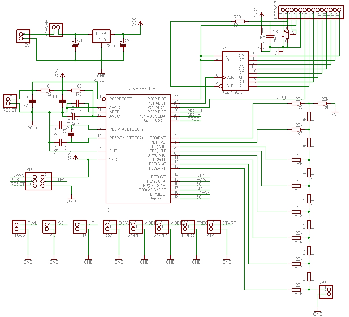
Buttons
There will be 7 buttons in AVR controlled signal generator. One will be a Reset button, which will be acting as a stop. Start button to start signal generation. Two buttons for selecting signal and its properties (MODE1, MODE2). FREQ button selects the signal frequency (ones, tens, hundreds) and two buttons to increase or decrease values (UP and DOWN).
There will also be going to be ISP header for in-circuit programming of the Atmega8 microcontroller.
Atmega8 will be clocked at a maximum 16MHz to reach maximum performance.
hello sir,
i am interested in your site,but please leave projects in compelet document.
I will do this once I finish my project.
So did you finished this project…? If you do, can i get some help (hex) to make my own…Thanks