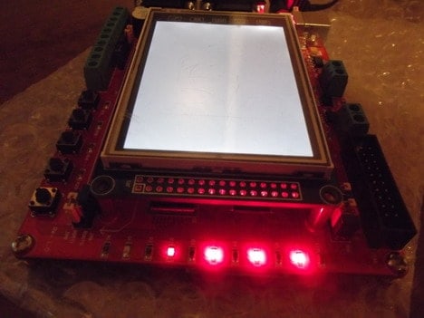
I found some time to play with the STM32F103ZET6 development board and decided to set up a simple project for it. The trickiest part of this is to set up a project environment that would serve as a template for the following developments. Many ARM developers chose the CodeSourcery Lite edition toolchain. It has full command line functionality – this is what we usually need. If you want some alternative – you can select gnu yagarto ARM toolchain, which is also great and free.
No matter which tool you select, the code will work on both. Let’s stick to CodeSourcery. Just download it and install it on your PC. As we said Lite version supports only command-line tools – we need an interface for it. Eclipse IDE is one of the favorite choices, so that we will grab this one too. Yagarto website has an excellent tutorial on how to set up the Eclipse IDE in a step-by-step manner. We won’t go into details with this.
Say we have a development environment up and running. There is still one piece needed – flash programming software. ARM Cortex-M3 microcontrollers come with a preloaded bootloader that allows uploading firmware via RS232 (or USART to USB converter). For this, ST has prepared a special software called Flash Loader Demonstrator. With it, you will be able to upload .hex files simply using an RS232 cable. Also, there are other options like using a Jtag adapter.
Now we can proceed to set up our project base. The compiler itself doesn’t know about the microcontroller you are using. This is why we have to define how much memory is available on the chip also outside of the chip. Then we need to indicate memory sections, stack, heap. We need to allocate the interrupt table in flash memory and do many other tasks before running an actual program. These tasks are described in the linker script and startup code. There is no need to write startup code and linker scripts from scratch. There are plenty of working examples on the internet. For this example, we will borrow these from Michael Fisher (STM3210ETest) used in Yagarto. Just be sure that Memory parameters are set correctly. In our case lines in files (stm32f103xe_flash.ld and stm32f103xe_ram.ld)should be:
MEMORY
{
FLASH (rx) : ORIGIN = 0x08000000, LENGTH = 512K
RAM (rwx) : ORIGIN = 0x20000000, LENGTH = 64K
}
Also, we will use Standard Peripheral Library, which will make it easier to program MCU peripherals as it has all necessary register definitions and CMSIS driver functions, allowing to access peripherals with unified functions. Currently, there is a v3.5.0 version of the library.
Now we have everything we need. Next, we open Eclipse IDE and go to the workbench where we select menu File->New. Enter the desired Project name. Then select Makefile->Empty project. In the toolchain, the list selects Other Toolchain. Click the Finish button.
In the project explorer, you should see the project folder with the selected name. We are going to make some folder structure so each library and device files wouldn’t mix.
Now we can start copying some files into directories. First of all from STM3210ETest package copy stm32f103xe_flash.ld and stm32f103xe_ram.ld files to linker directory. Then crt.c and vectors_stm32f10x_hd.c copy to startup directory. Next, we need to copy CMSIS and STM32F10x_StdPeriph_Driver folders as follows:
According to stm32f10x.h file we also need stm32f10x_conf.h file where we need to include necessary peripheral library headers. You can find this file in the STM3210E-EVAL package. Place this file in the root directory. You can also grab stm32f10x_it.h and stm32f10x_it.c files where we will write our future interrupt handlers.
Now we create main.c in the project root directory, where we will write our code. And, of course, you will need a makefile to compile the project. You will find it in a project package as it takes quite a significant space. As we are going to blink LEDs, this time, let’s create a driver. In Drivers, the directory adds two now source files leds.c and leds.h. Now we have a complete project template that we can use for most of the projects.
First of all, take care of the LEDs driver. All we need is to initialize pins where LEDs are connected. For this we make a function:
void LEDsInit(void)
{
  //GPIO structure used to initialize LED port
  GPIO_InitTypeDef GPIO_InitStructure;
  //Enable clock on APB2 pripheral bus where LEDs are connected
  RCC_APB2PeriphClockCmd(LEDPORTCLK,  ENABLE);
  //select pins to initialize LED
  GPIO_InitStructure.GPIO_Pin = LED1|LED2|LED3|LED4|LED5;
  //select output push-pull mode
  GPIO_InitStructure.GPIO_Mode = GPIO_Mode_Out_PP;
  //select GPIO speed
  GPIO_InitStructure.GPIO_Speed = GPIO_Speed_50MHz;
  GPIO_Init(LEDPORT, &GPIO_InitStructure);
  //initially LEDs off
  GPIO_SetBits(LEDPORT, LED1|LED2|LED3|LED4|LED5);
}
As you can see, peripherals are initialized through structures. To initialize ports, we create the GPIO_InitTypeDef variable where we define variables and then pass a structure as a parameter to the GPIO_Init function. To configure the port, we select what pins we are going to use. Then we choose pin mode (in our case, its push-pull output) and then select the maximum speed.
But before we do initialization, we need to enable the port bus clock. As the LED port is connected to the APB2 bus, we use the RCC_APB2PriphClockCmd function to enable this port.
After LEDs are initialized we can turn them on, turn off and toggle with the following functions:
voidLEDOn(uint32_t);
voidLEDOff(uint32_t);
voidLEDToggle(uint32_t);
To control port pins we are using atomic bit manipulation with functions:
GPIO_SetBits(LEDPORT, LED1);
GPIO_ResetBits(LEDPORT, LED4);
GPIO_ReadOutputDataBit(LEDPORT, LED3);
After LEDs driver is ready we can write a simple program that sweeps all 5 LEDs:
//running LEDs
#include "stm32f10x.h"
#include "leds.h"
//delay function
void Delay(__IO uint32_t nCount)
{
  for(; nCount != 0; nCount--);
}
int main(void)
{
  //init leds
  LEDsInit();
while (1)
  {
	LEDToggle(1);
	Delay(500000);
	LEDToggle(2);
	Delay(500000);
	LEDToggle(3);
	Delay(500000);
	LEDToggle(4);
	Delay(500000);
	LEDToggle(5);
	Delay(500000);
  }
}
All is left to connect the board to a computer with RS232 cable and upload .hex to microcontroller flash memory.


