
STM32F103R board is a simple and easy development board to learn STM32 microcontroller programming. Its heart is an STM32F103RBT6 ARM Cortex-M3 microcontroller with 128K of Flash and 20K of SRAM memory. It can be clocked at the maximum 72MHz frequency and considered a medium-density performance line microcontroller. Other features include USB, CAN, seven timers, 2ADCs, and nine communication interfaces.
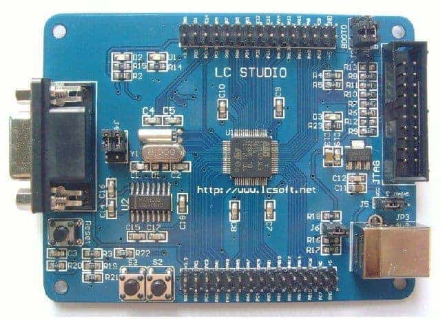
The Development board has several excellent features to get started. First of all, it has an RS232 interface for communicating and accessing the bootloader. There also is a USB 2.0 full-speed interface connector that also can work as the power supply. Next is a JTAG connector to program microcontroller using tools like a J-Link adapter. Two pushbuttons and two programmable LEDs are hardwired to MCU pins alongside all I/Os connectors.
To start programming this microcontroller, we need to set up a project template that can be used for further developments. We like GCC tools, so grab Sourcery CodeBench Lite Edition and Eclipse IDE to get started.
We won’t be reinventing the wheel and stick to what’s been done. As a reference, we can take our previous project on STM32F103ZET6 development board. The main difference between those microcontrollers is that the current is medium-density and earlier were high-density with more features and more memory. So few minor changes have to be done in the linker script and interrupt vectors table. As always, Michael Fischer has done the hard work and prepared those files. To get these, you can download STM32F103RB project files for Yagarto and extract files. We will need stm32f103xb_flash.ld and stm32f103xb_ram.ld and make sure that the memory configuration is proper:
MEMORY
{
FLASH (rx) : ORIGIN = 0x08000000, LENGTH = 128K
RAM (rwx) : ORIGIN = 0x20000000, LENGTH = 20K
}
Also, we will need crt.c and vectors_stm32f10x_hd.c files (Don’t worry you will find all files in a project package). The rest procedure is the same as in the STM32F103ZET6 project mentioned earlier. Let’s focus on hardware programming. First of all, let’s take care of the buttons. Here on board are two push buttons connected between PC0 and PC1 pins and ground:

Using CMSIS writing button driver is easy. First buttons.h file:
#ifndef BUTTONS_H_
#define BUTTONS_H_
#include "STM32f10x.h"
#define BS2 				GPIO_Pin_0
#define BS3 				GPIO_Pin_1
#define BPORT				GPIOC
#define BPORTCLK			RCC_APB2Periph_GPIOC
void ButtonsInit(void);
uint32_t ButtonRead(GPIO_TypeDef* Button_Port, uint16_t Button);
#endif /* BUTTONS_H_ */
Then we can write functions in buttons.c file:
#include "buttons.h"
void ButtonsInit(void)
{
  //GPIO structure used to initialize Button pins
  GPIO_InitTypeDef GPIO_InitStructure;
  //Enable clock on APB2 pripheral bus where buttons are connected
  RCC_APB2PeriphClockCmd(BPORTCLK,  ENABLE);
  //select pins to initialize S2 and S3 buttons
  GPIO_InitStructure.GPIO_Pin = BS2|BS3;
  //select pull-up input mode
  GPIO_InitStructure.GPIO_Mode = GPIO_Mode_IPU;
  //select GPIO speed
  GPIO_InitStructure.GPIO_Speed = GPIO_Speed_50MHz;
  GPIO_Init(BPORT, &GPIO_InitStructure);
}
uint32_t ButtonRead(GPIO_TypeDef* Button_Port, uint16_t Button)
{
  return !GPIO_ReadInputDataBit(Button_Port, Button);
}
When initializing buttons, we first enable the APB2 peripheral clock, then we set internal pull-up resistors for button pins and set I/O speed.
Next, we can write LED drivers. LEDs are connected between PB8, PB9, and VCC as follows:
Initialize LEDs with the following function in leds.c:
void LEDsInit(void)
{
  //GPIO structure used to initialize LED port
  GPIO_InitTypeDef GPIO_InitStructure;
  //Enable clock on APB2 pripheral bus where LEDs are connected
  RCC_APB2PeriphClockCmd(LEDPORTCLK,  ENABLE);
  //select pins to initialize LED
  GPIO_InitStructure.GPIO_Pin = LED1|LED2;
  //select output push-pull mode
  GPIO_InitStructure.GPIO_Mode = GPIO_Mode_Out_PP;
  //select GPIO speed
  GPIO_InitStructure.GPIO_Speed = GPIO_Speed_50MHz;
  GPIO_Init(LEDPORT, &GPIO_InitStructure);
  //initially LEDs off
  GPIO_SetBits(LEDPORT, LED1|LED2);
}
and implement three control functions:
voidLEDOn(uint32_t);
voidLEDOff(uint32_t);
voidLEDToggle(uint32_t);
To test if everything works, we can write a simple routine in main.c:
#include "stm32f10x.h"
#include "leds.h"
#include "buttons.h"
//delay function
void Delay(__IO uint32_t nCount)
{
  for(; nCount != 0; nCount--);
}
int main(void)
{
  //init leds
  LEDsInit();
  ButtonsInit();
while (1)
  {
	//read S2 button
	if (ButtonRead(BPORT, BS2))
	{
		//led 1 on
		LEDOn(1);
		//delay
		Delay(2000000);
		//led 1 off
		LEDOff(1);
	}
	//read S3 button
	if (ButtonRead(BPORT, BS3))
	{
		//led 2 on
		LEDOn(2);
		//delay
		Delay(3000000);
		//led 2 off
		LEDOff(2);
	}
  }
}
Here we turn the LED after the button is pressed, and it turns off automatically after some delay.
When compiling the program with the newest CodeBench Lite strange error popped out:
Error: registers may not be the same -- `strexh r0,r0,[r1]'
Error: registers may not be the same -- `strexb r0,r0,[r1]'
Arm specification requires that the Rd register be different from Rt and Rn and that CMSIS seems not to follow this. So to fix this, you need to modify core_cm3.c file as follows:
replace:
uint32_t __STREXH(uint16_t value, uint16_t *addr)
{
uint32_t result=0;
__ASM volatile ("strexh %0, %2, [%1]" : "=r" (result) : "r" (addr), "r" (value) );
return(result);
}
with
uint32_t __STREXH(uint16_t value, uint16_t *addr)
{
//uint32_t result=0;
register uint32_t result asm ("r2");
__ASM volatile ("strexh %0, %2, [%1]" : "=r" (result) : "r" (addr), "r" (value) );
return(result);
}
and replace:
uint32_t __STREXB(uint8_t value, uint8_t *addr)
{
uint32_t result=0;
__ASM volatile ("strexb %0, %2, [%1]" : "=r" (result) : "r" (addr), "r" (value) );
return(result);
}
with:
uint32_t __STREXB(uint8_t value, uint8_t *addr)
{
//uint32_t result=0;
register uint32_t result asm ("r2");
__ASM volatile ("strexb %0, %2, [%1]" : "=r" (result) : "r" (addr), "r" (value) );
return(result);
}
For more information refer to old.nabble.com. After this change code compiles fine. Flash microcontroller using Flash loader demonstrator or via JTAG and run. Download project template if you want to try it by yourself: [STM32F103R_Buttons_LEDs ~660K]