
I decided to make a pretty simple but powerful enough audio amplifier. For this, I’ve chosen quad-bridge car audio amplifier IC – TDA7384, which has four input and four output channels with a power capability of 4x35W.

If connected to a car battery where the operating voltage is about 13.2V, then each channel can give 22W what is more than enough for me. This amplifier I probably will use to test audio processor TDA7313, which is still in the development phase. I didn’t find much information about this chip on the internet, so I decided to build it and try it independently.
As datasheets of TDA,7384 says, low distortion, low output noise, and low external component count. It also has a Stand-By function and a Mute function. It has several protections like from output short circuit to GND. or to Vs., capable of handling very inductive loads, thermal limiter, load dump voltage. TDA7384 is an AB power amplifier cased in flexiwatt25 (eagle library is included in project archive) package designed for high-end car radio applications. It allows the rail to rail output voltage swing with no need for bootstrap capacitors.

I have followed the schematic in the datasheet when building a circuit. You may also find the PCB layout in the datasheet, but it is two-layered and didn’t fit the box I’ve chosen. So I have made a single-sided PCB 50X100mm.

As I put pins on PCB for ST-BY and Mute but I not using them, I connected these pins to VCC like it is shown in PCB view. According to the datasheet, St-By and Mute turn off the amplifier if the input signal is lower than 3.5V. So it is recommended to connect these pins to Vcc if not used.
The maximum power dissipation of the chip is 80W(Tcase=70ºC), so it can handle four channels working at a power of 20W each. But of course, a chip in a box doesn’t have proper ventilation, so I’ve put a radiator to ensure that the amplifier effectively dissipates heat. I didn’t try to load the amplifier to the maximum to see if it doesn’t heat up too much. But at a reasonable sound level, it stays warm what is normal.
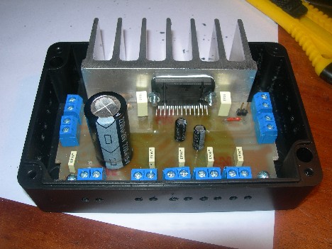
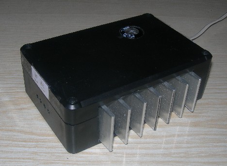
Don’t forget to put thermal paste between the chip and radiator to ensure lower thermal resistance. And here we go -“ brand new power amplifier ready to go:
When I will try it more, I will write comments on it.
Project files are here: TDA7384 Eagle Files.
Hi,
Great project, I am in need of a simple 10 – 20 watt amplifier for a small mono digital recorder. I want the output to drive a regular stereo speaker. It also needs to run off of 12VDC – 15VDC and less than 2 AMPS if possible. I am a beginner but am having fun learning, I bought DIPTrace, to learnhow to make my own circuit boards.
Where did you get that heat sink?
Really great job!
If you don’t need four separate channels, then I recommend to use simpler chip like TDA8560Q or less powerful stereo amplifier.
I have bought raw heat-sink at local market place and cut off a part. If you are not going to drive at near maximum power, then you don’t need big heat-sink, as chip can handle up to 80W without it. But of course there should be air circulation and so on. so it is better to use one.
I had a chance to connect this amplifier to a car audio. I can say that sound is pretty clean, and powerful, but not enough for a good acoustic system. There could be more low frequencies in my opinion. But again, this is low budget amplifier. If you need more quality and power better try something different.
Hi, I am thinking to use something like that pcb amplifier into a car audio system.
I need to be as small as possible and I would like to get the same quality and power of any car radio unit without extra amplifier and to be used with the car standar audio system. Could quality and power be increased using a different audio processor? Thanks.
Nice project. Planning to add it to my car as part of its restoration process. A few questions please. Can the amp channels be bridged from 4 to 2 in order to increase it power output?
tanx…
Lovely circuit. Worked perfectly on the first try. Thoug its not as loud as I would have loved and I’m still open to suggestions on how its poer could be increased. Any Ideas?
—Lovely circuit. Worked perfectly on the first try. —Thoug its not as loud as I would have loved and —I’m still open to suggestions on how its poer —could be increased. Any Ideas?
Replace the chip with the 7386 to get more wattage, be sure to read the data sheet to make appropriate changes. A higher yield approach would be to get more efficient speakers. Every 3db in efficiency is like doubling amplifier power.
hi guys. i used tda7384 for amp. It was working fine for d last 6 mnths but now it is giving prob. its dat wen i increase the ip level(increase d sound of input source dat is i conn SE w300i mobile)d sound distorts.it works fine on low ip level.
so i decided to make new amp of tda 7386. it worked fine.but wen i increase the ip level the amp skips the sound in between.(like on cell phone sound skips due to poor coverage). i connected portable dvd player as source but same prob. with mobile it used to work fine now i dnt know wat happend.plz help me out.thanks…
A great way to buy car audio on a budget is to buy used equipment. Depending on the type of equipment and the history of the unit it may be a great value or it may complete junk.
A great way to buy car audio on a budget is to buy used equipment
hi there
nice and easy chip but i have a question and execuse me i’m a bigenner most of audio sources provides only 2-channels like sound card , so9 when i make these 2-channels as input to the amp how can i use the other remaining 2-channels where it’s a 4-channel amp?
How much is the IC TDA7384 I need ten and how man
days is the shipping I am in UK
Thank you
i want a buy a TDA7384 but i cant find it from sri lanka can u help me pls
I will try this one of these days. If you get the chance, check out some of our Ford Mustang Subwoofer boxes at our site.
hi im a noob please tell me how to add a 10k pot for a volume control commonly for all four channels
hey,i don’t know much but what i’ve seen is that, on other pcb’s the output routes are thicker. are those to thin? or does it work alright?
Hi,
I have tried this project for over 6 times now but I have only succeded twice, have you noticed that the IC is too sensitive such that it doesn’t tolerate any slight mistakes? Dispite all this failure,I like the project,it’s easy to build,quality audio output and portable.
This amplifier still plays in old Nissan without no problem.
THIS IS GREAT i need 1 to buy as soon as possible plz notify me as soon as u get this thankx
gracias por el consejo
Great project for amp within low cost, although not so loud. But not bad.
Thanks for sharing this project.