What is DebugWire interface
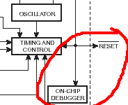
Debug wire is an interface that enables debugging AVR microcontrollers by using one wire. All new AVR microcontrollers with less than 16kByte memory have a built-in one-wire bidirectional debugging interface that allows debugging devices in real-time. Like the JTAG interface, DebugWIRE can handle full execution and program flow control. It also supports an unlimited number of breakpoints, adjusting memory contents. The good thing is that interface doesn’t require additional pins as only the RESET pin is used for debugging purposes.