Using FreeRTOS kernel in AVR projects

FreeRTOS is known as Real-Time Operating System. It would probably be too dare to call it real-time-os, preferably a real-time scheduler where applications can be split into independent tasks that share complete processor resources by switching them rapidly. It. It looks like all functions are executed in parallel. This feature is called multitasking. There are many debates on using RTOS on AVR microcontrollers as they are arguably too small for the running scheduler. The main limitation is a small amount of ram and increased power usage. If you use lots of tasks in the application, you will probably run out of RAM to save context when switching between tasks. Consider FreeRTOS only if you use larger scale AVRs like Atmega128 or Atmega256. Indeed you can find smaller schedulers that are specially designed for smaller microcontrollers, even tiny series. On the other hand, if you master FreeRTOS, it can be used with multiple microcontrollers like ARM Cortex, PIC, and various compilers, including IAR, GCC, and Keil Rowley, Attolic. And the main reason to keep an eye on it – it is free. Probably it would take lots of time and space to go through RTOS theory. Some great information can be…

Continue reading

How to drive servo motor control with AVR microcontroller

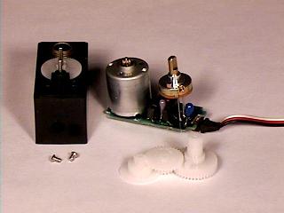
Servo motors are so-called “closed feedback” systems. This means that the motor comes with a control circuit inside, which senses if the motor mechanism is in the desired position. If not, it continuously corrects an error until the motor reaches the angle. Servo motors are widely used in robotics, remote-controlled planes, vehicles, and many other industrial machines. They come in many shapes and sizes, but they all operate in almost the same way. Usually, servo motors are controlled by a computer, microcontroller, or even a simple timer circuit. How Servo Motor Control Works Usually, servo motors are put in the plastic box, but inside there is a whole system: motor itself, gears, and motor driving and control circuit. The gears reduce motor speed but increase torque. As we mentioned, servos work with a closed feedback loop when the potentiometer is connected to a mechanical shaft and senses the angle of turn. The potentiometer voltage directly indicates the grade of twist. The potentiometer signal goes to a digital controller of the motor, which powers the motor until the potentiometer reaches the desired angle, then the logic circuit shuts the motor.

Continue reading

How to write an LCD menu for AVR in C

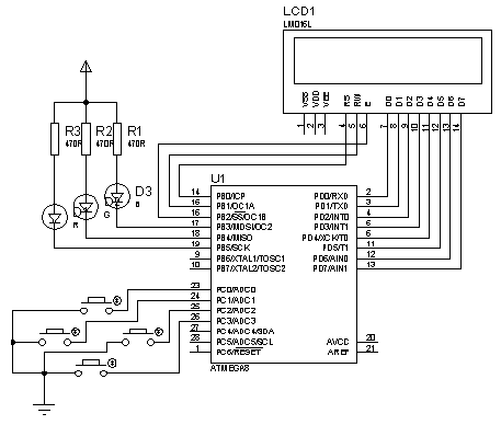
Let us write a simple LCD menu for AVR. I am using four buttons: 2 for menu scrolling up and down and two for changing submenu parameters. As the output indicator, I am using three LEDs that flash according to the menu’s parameters. Button states are captured by using timer0 overflow interrupts. The circuit is elementary:  I have excluded the power circuit for simplicity, just left the main parts: LCD, LEDs, and buttons. This circuit works well with the Proteus simulator as it is. The Proteus circuit is attached to the project archive. My idea is to store menu strings in Flash memory without occupying MCU RAM. This way, menu items are limited only by Flash memory, not by RAM.

Continue reading

AVR-GCC 4-bit and 8-bit LCD library

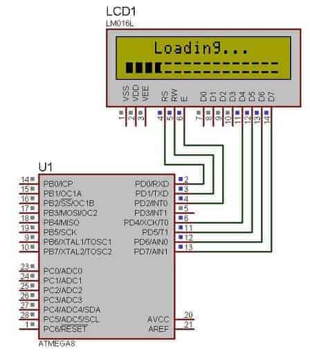
Earlier I have used 4-bit and 8-bit LCD libraries in various projects. It was hard to maintain and update. Now they are merged into one library where the simple logic structure is implemented to select a 4-bit or 8-bit LCD library just by modifying only three code lines. In the library header file there is line added: //Uncomment this is LCD 4 bit interface isused //****************************************** #define LCD_4bit //****************************************** You can select different LCD modes by commenting and uncommenting this line. Also, don’t forget to select proper ports and pins where the LCD is connected:

Continue reading

Adding external memory to Atmega128

Atmega128 is equipped with internal 4Kbytes of SRAM memory. Is it enough? Well, it depends on what project it’s going to hold. If your project must deal with loads of data or run more extensive RTOS code, you will run out of RAM pretty soon. Atmega128 microcontroller has an external memory interface built-in, which allows expansion of RAM up to 64 Kbytes. With that, you could do much more. I used the Piconomic Atmega128 development board to test things out, which has an XMEM interface header brought out. All we need is to make an XMEM expansion board with some SRAM memory. I’ve chosen a standard 8Kx8 (8Kbytes) memory chip from Alliance Memory Inc. I could use 64Kx8, but this is what I had at the moment. To drive the memory chip, I’ve used a 74HC573 non-inverting latch. As you may know, the latch is used for pins that share the same pins for address and data buses. To access SRAM contents, we need to select a 16-bit address pointing to an 8-bit data cell in the chip. As we are using an 8Kx8 memory chip, we are going to use only 13Address lines. The microcontroller has dedicated pins for…

Continue reading

Running TX433 and RX433 RF modules with AVR microcontrollers

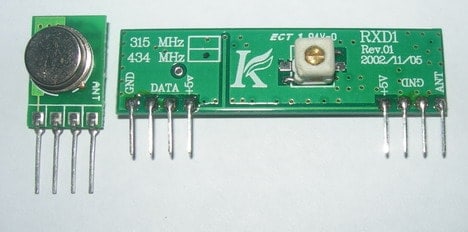
Sometimes in embedded design, you may want to go wireless. Maybe you will want to log readings of remotely placed sensors, or build a remote control for a robot or design an alarm system. Radio communications between two AVR microcontrollers can be easily set up with specialized modules. Let us try to run very well-known RF modules TX433 and RX433 (or similar) that can be found almost in every electronics shop. The pair of them cost less than 15 bucks. Transmitter and receiver modules are tuned together to work correctly at the exact 433.92MHz. The transmitter can be powered from a 3 to 12V power supply while the receiver accepts 5V. The 5V is standard for AVR microcontrollers, ideal for 5V devices. Modules do not require additional components – apply power and connect a single data line to transmit data.

Continue reading

Yet Another Simple AVR ISP cable

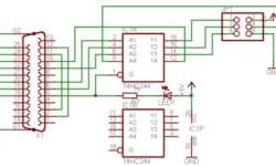
Probably this programmer cable can be found on every AVR fan website. It is straightforward and easy to build. You need a few passive components that can be packed inside the LPT connector. From my perspective, I wouldn’t recommend using this one ISP programmer if you are more serious about microcontroller projects because it has poor computer port protection. It connects directly to the LPT port without precautions. I recommend using a similar ISP circuit with buffer IC between LPT and target board. But let’s don’t pretend like we are brilliant. The whole beauty is in its simplicity. This thing does its job perfectly as long as the target board power supply is OK.

Continue reading

USB bootloaders for AVR microcontrollers

Probably the most proper microcontroller programming method is using a bootloader program. Because you don’t need any special programming adapters or special knowledge – you need to connect a standard cable from your PC to the target board and run a special program on the PC which communicates with the MCU bootloader program. The idea is simple: If the microcontroller is preconfigured, then after reset, it starts running not from the start memory location, which is usually at 0x0000 address, but at some specific location, where usually bootloader lies.

Continue reading

AVR DDS signal generator V2.0

Finally, the second version of the improved AVR DDS signal generator is here. THE first AVR DDS V1.0 generator was only an attempt to run the DDS algorithm without any analog amplitude control. In this DDS generator version, I still wanted to keep things as simple as possible using a minimum count of widely available components in the updated circuit. Also, I kept a single-sided PCB approach. AVR DDS specification AVR DDS signal generator V2.0 is a firmware-based DDS signal generator that uses a slightly modified Jesper’s mini DDS algorithm adapted to AVR-GCC C code as in-line ASM. The AVR DDS signal generator has two outputs – one for DDS signal and another for high speed [1, 8MHz] square signal – which may be used to bring back to life microcontrollers with wrong fuse settings for other purposes where a high-speed square signal may be needed. A high-speed (HS) signal is output directly from the Atmega16 OC1A(PD5) pin. The DDS output is used for all complex signals generated via the R2R resistor network and is adjusted via LM358N offset and amplitude regulating circuits. Two potentiometers can control offset and amplitude. The offset can be controlled in range +5V..-5V while magnitude…

Continue reading

Programming AVR ADC module with avr-gcc

Most AVR microcontrollers have Analog to Digital Converter (ADC) integrated into to chip. Such a solution makes embedded designers’ life much easier when creating projects and programming them. With no need for external ADC, PCB takes less space, easier to create programs – it saves time and money. As an example, let’s take the Atmega8 microcontroller, which has up to 8 ADC inputs, most with a 10-bit resolution(excluding ADC4 and ADC5 inputs that are 8-bit). All features of AVR internal ADC can be found on official ATMEL AVR datasheets, but most important to mention are: ±2 LSB accuracy – so measurements aren’t very accurate. If AREF voltage is 5V, then the error may reach ±0.04V, but this is still good results for most of the tasks; Integral nonlinearity ±0.5 LSB; Conversion speeds up to 15kSPS at maximum resolution. This is far not enough for 20kHz audio signal sampling.

Continue reading