Implementing buttons on STM32F103ZET6
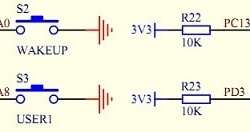
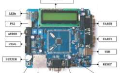
Last time we have made a good starting point with setting up a project template for the STM32F103ZET6 development board using GNU tools. Using the same project template, we can move forward and start programming other elements. This time a quick note about adding a button library. This is a modest implementation that initializes port pins and then reads their status. The Development board is equipped with four user-programmable buttons named WAKEUP, TAMPER, USER1, and USER2. We will not care about the meaning of names; use them as general-purpose buttons for now.