
Dallas Semiconductor, owned by Maxim, developed the 1-Wire communication protocol. This protocol allows the communication of multiple chips to one host with minimal pin count. The protocol is called 1-Wire because it uses 1 wire to transfer data. The 1-Wire architecture uses a pull-up resistor to pull the data line’s voltage at the master side.
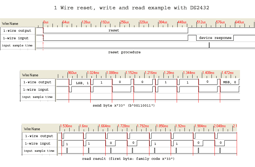
1-Wire protocol uses CMOS/TTL logic and operates at a supply voltage range of 2.8 to 6V. Master and slave can be receivers and transmitters, but only one direction at a time. LSB goes first always. Time slots transfer data in the 1-wire network. For instance, to write logic “1”, the master pulls the bus low for 15us or less. To write logic “0,” the master pulls buss low for at least 60us. The system clock is not required as each part is self-clocked and synchronized by the falling edge of the master.
Before communicating master resets the network by holding the bus low for at least 480us and then looking for a responding pulse from slaves. Then master calls the slave by its address, which is unique for each slave device.
Each device has 48 bits (six bytes) globally unique addresses where the last eight bits are CRC of the first 56 bits. First, byte stores a device family code that identifies device type.
When there is more than one chip in a 1-wire circuit, it is called a 1-wire network or so-called MicroLAN. This network requires one master and at least one slave. Standard allows putting as many slaves as you want, but their communication problems may occur when this number exceeds 20. Wire length connecting slaves to master may be up to 200m. The longer line, the better care should be taken, like avoid crossing with power lines. For longer cables cheapest and easiest solution is to use the CAT5 cable that is used for LAN.
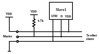
1-wire normal mode
Usually 1-Wire devices are connected using three leads (Power, Data, GND)
Parasite mode
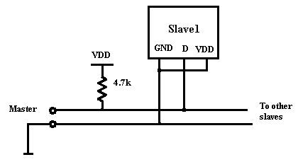
In this mode chips gets power from data line. This allow eliminating external power. But this mode have few disadvantages like:
- More delayed process;
- During parasite mode communication master cannot speak to other slaves;
- Some chips may lose data because of no power. So each time, they have to be reconfigured.
Sometimes the good solution is to put the backup battery on the slave side to save counter data. The parasitic mode is useful when interfacing in long distances because resetting of devices is easy -just pulling down the data-line.